Download presentation
Presentation is loading. Please wait.

1
Interrupt Interrupt – to break the flow of speech or action of (someone) by saying or doing something (Longman dictionary)
 by saying or doing something (Longman dictionary)")
2
Examples When your phone rings during a lecture, what will happen?
When you are studying then your cell phone rings – what will you do? When you finish talking on the phone then you will continue with your study Now your phone rings again and someone also knocking at your door then what will you do? When being interrupted, you will perform some pre-defined action Interrupt has priority – some interrupt is more important than the others. For example, asking your phone is more important than opening the door

3
Interrupts Interrrupt is a procedure that interrupts whatever program
is currently executing by the CPU. Interrupts are particularly useful when interfacing I/O devices that provide or require data at relatively low data-transfer rates , eg a keyboard. During an interrupt, the CPU will perform pre-defined operations according to the interrupt nature so the microprocessor can execute other software before the interrupt occurs

4
Interrupt Once the CPU is interrupted then it will perform the pre-defined operation according to the interrupt nature

5
Use of interrupt How to get key typed in the keyboard or a keypad?
Polling The CPU executes a program that check for the available of data If a key is pressed then read the data, otherwise keep waiting or looping!!! Just like the mechanism used in LAB for sensing the keypad Interrupt The CPU executes other program, as soon as a key is pressed, the Keyboard generates an interrupt. The CPU will response to the interrupt – read the data. After that returns to the original program. So by proper use of interrupt, the CPU can serve many devices at the “same time”

6
interrupt Doing Something else No key pressed Do key pressed action Polling

7
Example of interrupt How to control a robot that has sensors to detect obstacles and makes a turn Polling Move forward in a pre-defined unit Check sensor reading Do nothing if no obstacle or turn if obstacle detected Loop back and move forward again

8
Interrupt Controlling a robot by interrupt
Keeping moving until interrupted by the sensor Interrupt received then do pre-defined operation After finishing the interrupt service return to normal operation ie keep moving forward again

9
Polling Vs Interrupt Control of a robot
Move forward Move forward Check sensor Y interrupt Stop or turn

10
Interrupt Vs Polling Which mechanism is better Why??????

11
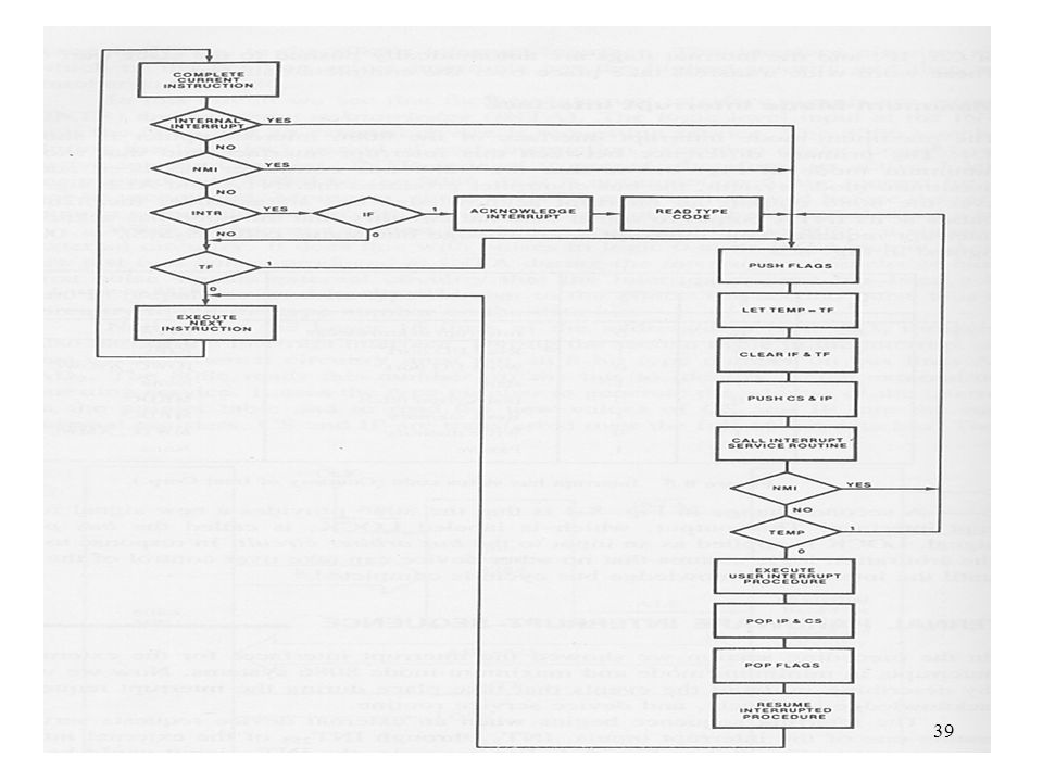
Introduction Interrupt can be caused by an external device or an internal event When interrupt occurs, program control is transferred from the original program to the Interrupt Service Routine (ISR) The mechanism is similar to a subroutine call. The CPU remembers the location where it left off in the original program and then picks up execution in the interrupt service routine. After this routine has run to completion, program control is returned to the point where the CPU originally was executing.
 The mechanism is similar to a subroutine call. The CPU remembers the location where it left off in the original program and then picks up execution in the interrupt service routine. After this routine has run to completion, program control is returned to the point where the CPU originally was executing.")
12
Program flow with interrupt
Original Program Interrupt occurs Interrupt service routine Return to the original program

13
Introduction to interrupt
8086 can implement 256 different types of interrupts The interrupts are divided into 5 groups Five groups: external hardware interrupt, software interrupts, internal interrupts, nonmaskable interrupt, and reset The interrupt routines for external hardware, software, and nonmaskable interrupts can be defined by user (you can write your own ISR)
")
14
Introduction to interrupt
When more than one interrupt occur then priorities of the interrupts are compared in order to determine which interrupt to serve first (open the door or answer the phone?)
")
15
Interrupt Priority Hardware, software, and internal interrupts are serviced on a priority basis Priority hierarchy groups: internal interrupt, nonmaskable interrupt, software interrupt, and external hardware interrupt Internal interrupt group has the highest priority External hardware interrupt group has the lowest priority Within a group, different interrupts have different priority levels represented by the type number (or interrupt number)
")
16
Interrupt priority Interrupt type Priority level Internal Highest
Non-maskable Very high software High External (32 – 255) low
 low.")
17
Interrupt priority Type 0 – highest priority
Type 255 – lowest priority Example – an internal interrupt, divide error, is a type 0 interrupt Divide error : divide by zero Overflow is type 4 When a CPU is performing an interrupt service routine, it can be interrupted by a higher priority interrupt. If a lower priority occurs, the newly occurred interrupt must wait

18
Multiple interrupt Interrupt by Higher priority Interrupt

19
Interrupt address pointer table
When interrupt occurs, CPU will perform some routine (function) How to locate the appropriate function or where is the function stored in memory???? In 8086, the interrupt address pointer table is serving as a link between the interrupt type numbers to the locations of their service routines in the program storage memory
 How to locate the appropriate function or where is the function stored in memory In 8086, the interrupt address pointer table is serving as a link between the interrupt type numbers to the locations of their service routines in the program storage memory.")
20
Interrupt Pointer Table
For 8086 the table is stored in memory location (address) 00H – 3FFH (1K) Address pointers identify the starting locations of their service routines in program memory For the 8086, each pointer requires two words (4 bytes) The higher address word is the base address and will be loaded into the CS register The lower address word is the offset address and loaded into the IP register
 00H – 3FFH (1K) Address pointers identify the starting locations of their service routines in program memory For the 8086, each pointer requires two words (4 bytes) The higher address word is the base address and will be loaded into the CS register. The lower address word is the offset address and loaded into the IP register.")
21
Function of the pointer table
Address of Service routine CS + IP Pointer table Interrupt Number/vector

22
Interrupt address table
Vector 0 = interrupt type 0

23
Example At what address should vector, CS50 and IP50 (ISR information for INT 50) be stored in memory ? This represent the interrupt level 50 Starting from 0 type 50 should be in 50x4 since each pointer requires 4 bytes In HEX, 200 is C8 to CB C8 stores the IP value, CA stores the CS

24
Interrupt instructions
Mnemonic Meaning Format Operation Flags affected CLI Clear interrupt flag IF = 0 IF STI Set interrupt flag IF =1 INT n Type n software interrupt TF, IF IRET Interrupt return ALL

25
Interrupt instructions
Mnemonic Meaning Format Operation Flags affected INTO Interrupt on overflow INT 4 if O = 1 TF, IF TF – trap flage HLT Halt Wait for an external interrupt or reset to occur None WAIT Wait Wait for /test input to go active

26
Interrupt instruction
Int 80 – calls the interrupt service procedure that begins at the address represented in vector number 80 Int 80 – allows you to execute the Interrupt service routine for interrupt 80 in your program

27
Interrupt request input (INTR)
How can an external device interrupt the CPU? The CPU has an input(s) pin for accepting the interrupt request signal For 8086, this input pin is called INTR (interrupt request)
 pin for accepting the interrupt request signal. For 8086, this input pin is called INTR (interrupt request)")
28
The Interrupt Flag If the interrupt flag (IF) is set (=1) then external hardware can initiate an interrupt via the INTR input of the microprocessor If IF flag is clear (=0) then the external device cannot initiate an interrupt During the initiation sequence of an interrupt service routine, the 8086 automatically clears IF. This masks out (disable) the occurrence of any additional external hardware interrupt. The IF flag should be re-enable at the end of the service routine
 then the external device cannot initiate an interrupt. During the initiation sequence of an interrupt service routine, the 8086 automatically clears IF. This masks out (disable) the occurrence of any additional external hardware interrupt. The IF flag should be re-enable at the end of the service routine.")
29
External hardware interrupt interface
An interrupt interface circuit is required to drive the INTR (Interrupt Request) input of the 8086 (WHY????) There is only 1 interrupt input in the 8086 The circuit will support interrupt 32 to 255 The circuit must identify which of the pending active interrupt has the highest priority and then pass its type number to the 8086 The 8086 samples the INTR input during the last clock period of each instruction execution cycle
 input of the 8086 (WHY ) There is only 1 interrupt input in the The circuit will support interrupt 32 to 255. The circuit must identify which of the pending active interrupt has the highest priority and then pass its type number to the The 8086 samples the INTR input during the last clock period of each instruction execution cycle.")
30
Interrupt interface Minimum mode

31
External hardware interrupt
INTR =1 implies an active interrupt request INTR is level-sensitive must be held at ‘1’ until it is recognized INTR signal must be clear before the service routine runs to completion; otherwise, the same interrupt may be acknowledged again

32
Interrupt interface INTA – interrupt acknowledge is used to inform the recognition of an interrupt Two pulses are produced at INTA during the interrupt acknowledge bus cycle The first pulse signals external circuit that the interrupt request has been acknowledged and to prepare to send the interrupt type number (or just the interrupt number) The second pulse tells the external circuit to put the type number on the data bus The type number is put on the bit 0 to 7 of the address/data bus
 The second pulse tells the external circuit to put the type number on the data bus. The type number is put on the bit 0 to 7 of the address/data bus.")
33
External Interrupt sequence
The interrupt sequence begins when an external device requests service by activating one of the interrupt inputs (32 to 255) External circuit evaluates the priority of the input If there is no interrupt already in progress and this interrupt is of higher priority than any other interrupt that is simultaneously active, the external circuit must issue a request for service to the 8086 INTR switches to 1
 External circuit evaluates the priority of the input. If there is no interrupt already in progress and this interrupt is of higher priority than any other interrupt that is simultaneously active, the external circuit must issue a request for service to the INTR switches to 1.")
34
Interrupt sequences 8086 checks the setting of the IF
If IF is 0 then no interrupt action will be performed If IF is 1 then external hardware interrupts are enabled and the service routine is to be initiated Interrupt acknowledge cycle is initiated T1 of the first bus cycle, address/data is put in the high-Z state and stays in this state for the rest of the cycle During T2 and T3, /INTA (active-low) is switched to 0. And the INTR can be removed
 is switched to 0. And the INTR can be removed.")
35
Interrupt sequences In the second interrupt acknowledge bus cycle, the INTA tells the external circuit to put the type number of the active interrupt on the data bus External circuit put the type number on the data bus. This must be valid during T3 and T4 DT/R, /DEN, and M/IO must set properly to read the type number from the data bus After reading the type number, the interrupt acknowledge part of the interrupt sequence is completed

36
Interrupt sequences After reading the type number, the corresponding interrupt service routine (ISR) is executed Flag register is saved in the stack IF is clear to disable other hardware interrupt TF is clear to disable single-step mode if it is active Current values of CS and IP are saved in the stack

37
Interrupt sequence The type number is internally multiplied by 4, and the result is used as the address of the first word of the interrupt vector in the pointer table Service routine is initiated IRET at the end of the service routine causes the old contents CS and IP to be restored

38
Interrupt acknowledge bus cycles
Note: /INTA is issued twice

40
Return to interrupted program
Before Acknowledge The IF flag must be 1 Ack Interrupt Type number is input at the 2nd INTA cycle Read Interrupt type Address of ISR is obtained by x4 the Interrupt type number and address the Interrupt pointer Table Call ISR IRET is reached Return to interrupted program

41
Interrupt service routine

42
Expanding interrupt input
Can accept 7 inputs the /IRX input is used for supplying the Type No Priority is Resolve by storing The ISR at the Proper location A buffer/latch

43
Interrupt interface requirements
Support a many-to-one configuration Able to issue the INTR signal Able to supply the interrupt number to the CPU Able to resolve priority issue

44
Interrupt interface using the NAND gate
The diagram in the previous page shows how to implement an interrupt interface using a simple NAND gate and a latch The number of interrupt that can be supported is 7 !!!! (D7 is always a ‘1’) The interrupt type number is derived from the active interrupt input For example, if IR0 is active then the interrupt type number is Using the previous circuit, can you handle two interrupts activated at the same time ?????
 The interrupt type number is derived from the active interrupt input. For example, if IR0 is active then the interrupt type number is Using the previous circuit, can you handle two interrupts activated at the same time")
45
Resolving Priority issue
When two IRs (interrupt requests) active at the same time then we must serve the one with higher priority first – execute the ISR for higher priority interrupt With the NAND gate and latch setup, we need to manipulate the interrupt pointer table
 active at the same time then we must serve the one with higher priority first – execute the ISR for higher priority interrupt. With the NAND gate and latch setup, we need to manipulate the interrupt pointer table.")
46
Resolving priority issue
If IR0 has a higher priority and if IR0 and IR1 active at the same time then the Interrupt type number received by the CPU is (FCH) CPU will go to location = FCH x 4 of the interrupt pointer table to look for the ISR If we put the address of ISR for IR0 in that location then ISR of IR0 will be executed and implying that IR0 has a higher priority!
 CPU will go to location = FCH x 4 of the interrupt pointer table to look for the ISR. If we put the address of ISR for IR0 in that location then ISR of IR0 will be executed and implying that IR0 has a higher priority!")
47
Self test What are needed into order to accomplish an interrupt mechanism? Can the circuit in the previous page support all the features? Can it activate the INTR? Can it produce the interrupt type number? Can it resolve priority issue?

48
Interrupt pointer table
Interrupt Number Address in HEX Content FEH 3F9 CDH 3F8 ABH DEH 379 378 Only IR0 active IR5 and IR0 active

49
Software interrupt 256 software interrupts (0 to 255)
Usage INT n , n is the interrupt type number During software interrupt, no external interrupt acknowledge bus cycles are initiated Control is passed to the start of the service routine immediately upon completion of execution of the interrupt instruction Software interrupts have a higher priority than external interrupts and cannot be masked out by IF

50
Nonmaskable interrupt (NMI)
NMI is another input pin in the 8086 to support nonmaskable interrupt. The other interrupt input is INTR NMI is also initiated from external hardware It cannot be masked out with the IF flag NMI interrupt will send a 1 to the NMI input of the 8086 NMI is positive edge triggered (low to high) NMI signal must be active for 2 consecutive clock cycles. Or must remain a ‘1’ until it is recognized by the microprocessor.
 NMI signal must be active for 2 consecutive clock cycles. Or must remain a ‘1’ until it is recognized by the microprocessor.")
51
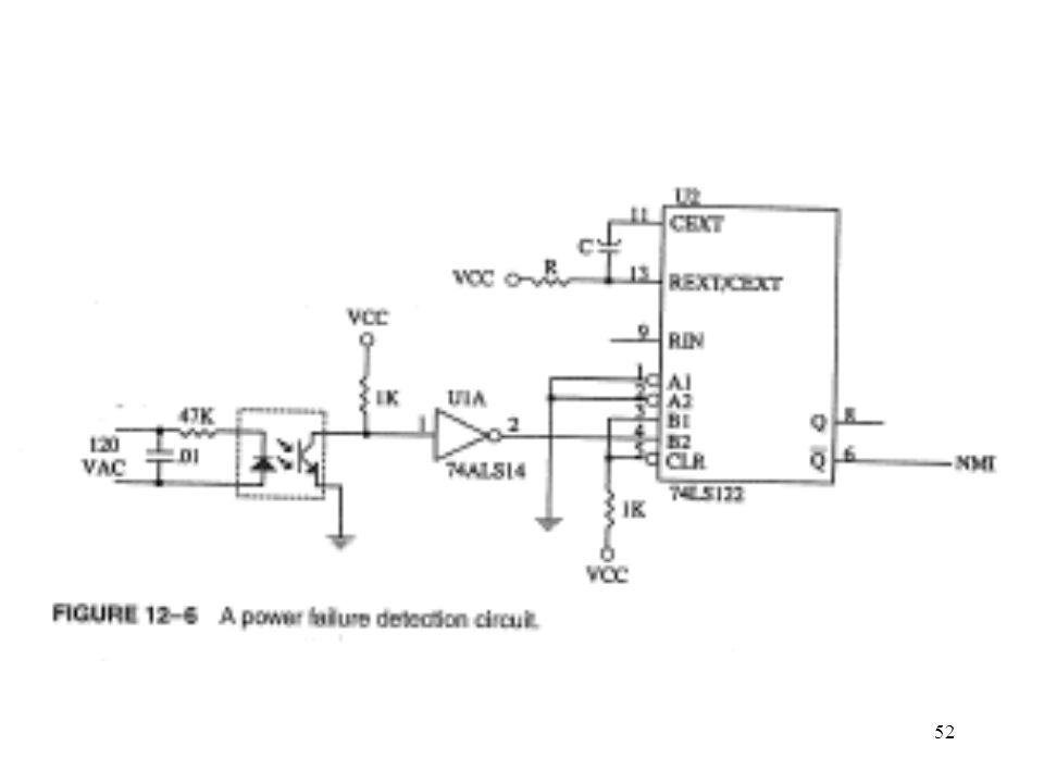
NMI NMI causes the current flags, current CS, and current IP to be pushed onto the stack Interrupt enable flag is cleared to disable all external hardware interrupts Single-step mode of operation is disable NMI is type 2 interrupt with a very high priority NMI is for hardware events that must be responded to immediately (major system faults), eg detection of power failure and detection of a memory read error
, eg detection of power failure and detection of a memory read error.")
53
8259A Interrupt controller
Instead of using a NAND gate and a latch, the interrupt mechanism is usually implemented with a more advanced digital device – Interrupt controller 8259A is a typical example 8259A is a hardware device to support the interrupt mechanism It can support up to 8 vectored priority encoded interrupts to the microprocessor Can be expanded (using more 8259) to accept up to 64 interrupt requests using master/slaves configuration
 to accept up to 64 interrupt requests using master/slaves configuration.")
54
8259A programmable interrupt controller
8259A is programmed via the microprocessor through the host processor interface The host interface consists of: data bus, read, write, interrupt request (INT), interrupt acknowledge (INTR) and chip select The data can be command words, status information, or interrupt type numbers. The INT and INTR are connected to the microprocessor. They are used for handshaking
, interrupt acknowledge (INTR) and chip select. The data can be command words, status information, or interrupt type numbers. The INT and INTR are connected to the microprocessor. They are used for handshaking.")
55
Pins assignment for 8259A

56
Interrupt controller INT generated by 8259 is connected to INTR of 8086 INT =1 when 8259 receives a valid interrupt request INTA produced by the microprocessor consists of two pulse and it signals the 8259 to put the interrupt type number on the data bus

57
Interfacing the 8259A to 8086 This is a PAL From the CPU’s point of
Cascading Using master Slave connection This is a PAL From the CPU’s point of View, the 8259 is also a I/O device!!!! How the 8259 is enabled?

58
Block Diagram of 8259A

59
Interrupt mask register
Interrupt mask register (IMR) can be used to enable or mask out individually the interrupt request inputs There are 8 bits and each bit represents one interrupt input 0- enable; 1- mask out (disable) The register can be read from or written into under software control (programmed via the microprocessor
 can be used to enable or mask out individually the interrupt request inputs. There are 8 bits and each bit represents one interrupt input. 0- enable; 1- mask out (disable) The register can be read from or written into under software control (programmed via the microprocessor.")
60
Interrupt request register (IRR)
IRR stores the current status of the interrupt request inputs Has one bit for each IR input The values in the bit positions reflect whether the interrupt inputs are active or inactive

61
Priority resolver The priority resolver identifies which of the active interrupt inputs has the highest priority The resolver can be configured to work using a number of different priority schemes through software It will signal the control logic that an interrupt is active and in response, the control logic causes the INT signal to be issued

62
8259 interrupt controller The in-service register (ISR) stores the interrupt level that is presently being serviced. During the first INTA pulse in an interrupt acknowledge bus cycle, the level of the highest active interrupt is strobed into ISR. The ISR cannot be written into by the microprocessor but its contents may be read as status The cascade buffer/comparator section provides the interface between master and slave 8259As. This permits easy expansion of the interrupt interface using a master/slave configuration

63
Connecting two 8259A

64
Master/slave

65
Summary Using interrupt allows CPU to serve many devices at the same time Different types – software, hardware Interrupt – has priority. Always serve the high priority first ISR – interrupt service routine tells the CPU what to do during an interrupt A table stores the locations (represented by the corresponding CS and IP values) of the ISRs
 of the ISRs.")
66
Summary INTR, NMI are inputs for external interrupt
INTA – output to acknowledge the interrupt and ask for the interrupt vector Interrupt controller is to expand the interrupt interface, resolve priority etc

Similar presentations


 is needed. Sources of interrupts: internal fault (e.g.. divide by.>")


