Download presentation
Presentation is loading. Please wait.

1
University Of Engineering And Technology Taxila REF::NATIONAL TAIWANOCEAN UNIVERSITY 國立台灣海洋大學 Chapter 3 JUMP, LOOP and CALL Instructions

2
Outlines Loop instructions Conditional jump instructions Conditions determining conditional jump Unconditional long & short jumps Calculate target addresses for jumps Subroutines Using stack in subroutines Crystal frequency vs. machine cycle Code programs to generate time delay

3
Looping

4
Loop inside a Loop (Nested Loop)
")
5
8051 Conditional Jump Instructions

6
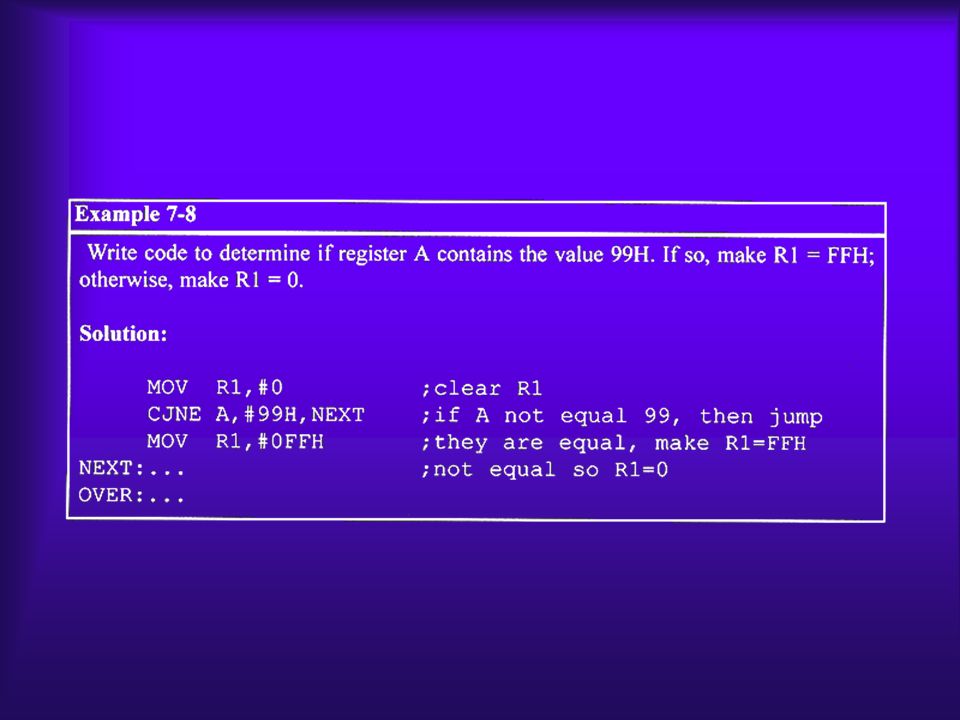
Conditional Jump Example

8
Unconditional Jump Instructions All conditional jumps are short jumps –Target address within -128 to +127 of PC LJMP (long jump): 3-byte instruction –2-byte target address: 0000 to FFFFH –Original 8051 has only 4KB on-chip ROM SJMP (short jump): 2-byte instruction –1-byte relative address: -128 to +127
: 3-byte instruction –2-byte target address: 0000 to FFFFH –Original 8051 has only 4KB on-chip ROM SJMP (short jump): 2-byte instruction –1-byte relative address: -128 to +127")
9
Call Instructions LCALL (long call): 3-byte instruction –2-byte address –Target address within 64K-byte range ACALL (absolute call): 2-byte instruction –11-bit address –Target address within 2K-byte range
: 3-byte instruction –2-byte address –Target address within 64K-byte range ACALL (absolute call): 2-byte instruction –11-bit address –Target address within 2K-byte range")
10
LCALL

11
CALL Instruction & Role of Stack

13
Calling Subroutines

15
ACALL (absolute call)
")
16
Programming Efficiently

17
Time Delay Generation & Calculation 1 instruction = n machine cycle 1 machine cycle = 12 clock cycles

18
Delay Calculation

19
Delay Calculation Example

21
Increasing Delay Using NOP

22
Large Delay Using Nested Loop

23
University Of Engineering And Technology Taxila REF::NATIONAL TAIWANOCEAN UNIVERSITY 國立台灣海洋大學 Chapter 6 Arithmetic Instructions and Programs

24
Outlines Range of numbers in 8051 unsigned data Addition & subtraction instructions for unsigned data BCD system of data representation Packed and unpacked BCD data Addition & subtraction on BCD data Range of numbers in 8051 signed data Signed data arithmetic instructions Carry & overflow problems & corrections

25
Addition of Unsigned Numbers ADDA, source; A = A + source

26
ADDC & Addition of 16-bit Numbers 1 3CE7 3B8D 7874 +

27
BCD Number System Unpacked BCD: 1 byte Packed BCD: 4 bits

28
Adding BCD Numbers & DA Instruction MOVA,#17H ADDA,#28H MOVA,#47H;A=47H first BCD operand MOVB,#25H;B=25 second BCD operand ADDA,B;hex (binary) addition (A=6CH) DAA;adjust for BCD addition (A=72H) HEXBCD 290010 1001 +18 +0001 1000 +18 +0001 1000 410100 0001AC=1 + 6 + 0110 + 6 + 0110 470100 0111
 addition (A=6CH) DAA;adjust for BCD addition (A=72H) HEXBCD AC=")
29
Subtraction of Unsigned Numbers SUBBA, source; A = A – source – CY SUBB when CY = 0 –Take 2’s complement of subtraend (source) –Add it to minuend –Invert carry
 –Add it to minuend –Invert carry")
30
Example (Positive Result)
")
31
Example (Negative Result)
")
32
SUBB When CY = 1 For multibyte numbers

33
Multiplication of Unsigned Numbers MULAB; A B, place 16-bit result in B and A MOVA,#25H;load 25H to reg. A MOVB,#65H;load 65H in reg. B MULAB;25H * 65H = E99 where ;B = 0EH and A = 99H Table 6-1:Unsigned Multiplication Summary (MUL AB) Multiplication Operand 1 Operand 2 Result byte byte AB A=low byte, B=high byte
 Multiplication Operand 1 Operand 2 Result byte byte AB A=low byte, B=high byte.")
34
Division of Unsigned Numbers DIVAB; divide A by B MOVA,#95H;load 95 into A MOVB,#10H;load 10 into B DIVAB;now A = 09 (quotient) and ;B = 05 (remainder) Table 6-2:Unsigned Division Summary (DIV AB) DivisionNumeratorDenominatorQuotientRemainder byte / byte ABAB
 and ;B = 05 (remainder) Table 6-2:Unsigned Division Summary (DIV AB) DivisionNumeratorDenominatorQuotientRemainder byte / byte ABAB")
35
Example ( 1 of 2 )
")
36
Example ( 2 of 2 )
")
37
Signed 8-bit Operands Covert to 2’s complement –Write magnitude of number in 8-bit binary (no sign) –Invert each bit –Add 1 to it
 –Invert each bit –Add 1 to it")
38
Example

39
Example

40
Example

41
Byte-sized Signed Numbers Ranges DecimalBinaryHex -1281000 000080 -1271000 000181 -1261000 001082 ….………….. -21111 1110FE -11111 1111FF 00000 000000 00000 000000 +10000 000101 +20000 001002 ……………... +1270111 11117F

42
Overflow in Signed Number Operations

43
When Is the OV Flag Set? Either: there is a carry from D6 to D7 but no carry out of D7 (CY = 0) Or: there is a carry from D7 out (CY = 1) but no carry from D6 to D7
 Or: there is a carry from D7 out (CY = 1) but no carry from D6 to D7.")
44
Example

45
Example

46
Example

47
University Of Engineering And Technology Taxila REF::NATIONAL TAIWANOCEAN UNIVERSITY 國立台灣海洋大學 Chapter 7 LOGIC INSTRUCTIONS AND PROGRAMS

48
Outlines Define the truth tables for logic functions AND, OR, XOR Code 8051 Assembly language logic function instructions Use 8051 logic instructions for bit manipulation Use compare and jump instructions for program control Code 8051 rotate and swap instructions Code 8051 programs for ASCII and BCD data conversion

49
AND XY X AND Y 000 010 100 111 ANL destination, source ;dest = dest AND source

50
OR ORL destination, source ;dest = dest OR source XY X AND Y 000 011 101 111

51
XOR XRL destination, source ;dest = dest XOR source XY X AND Y 000 011 101 110 XRLA,#04H;EX-OR A with 0000 0100

52
XOR

53
XOR

54
CPL (complement accumulator) MOVA,#55H CPLA;now A=AAH ;0101 0101(55H) becomes ;1010 1010 (AAH)
 MOVA,#55H CPLA;now A=AAH ; (55H) becomes ; (AAH)")
55
Compare instruction CJNE destination, source,relative address

56
Table 7-1:Carry Flag Setting For CJNE Instruction Compare Carry Flag destination > source CY = 0 destination < source CY = 1 CJNER5,#80,NOT_EQUAL;check R5 for 80 ….;R5=80 NOT_EQUAL:JNCNEXT;jump if R5>80 ….;R5<80 NEXT:….

61
Rotating the bits of A right and left RRA;rotate right A MOVA,#36H;A=0011 0110 RRA;A=0001 1011 RRA;A=1000 1101 RRA;A=1100 0110 RRA;A=0110 0011 RLA;rotate left A

62
MOVA,#72H;A=0111 0010 RLA;A=1110 0100 RLA;A=1100 1001

63
Rotating through the carry RRC A;rotate right through carry CLRC;make CY=0 MOVA,#26H;A=0010 0110 RRCA;A=0001 0011 CY=0 RRCA;A=0000 1001 CY=1 RRCA;A=1000 0100 CY=1 RLCA;rotate left through carry

64
SETBC;make CY=1 MOVA,#15H;A=0001 0101 RLCA;A=0010 1010 CY=0 RLCA;A=0101 0110 CY=0 RLCA;A=1010 1100 CY=0 RLCA;A=0101 1000 CY=1

65
SWAPA

67
RRCA;first bit to carry MOVP1.3,C;output carry as data bit RRCA;second bit to carry MOVP1.3,C;output carry as data bit RRCA;third bit to carry MOVP1.3,C;output carry as data bit …..

68
BCD AND ASCII APPLICATION PROGRAM

69
Packed BCD to ASCII conversion Packed BCDUnpacked BCDASCII 29H02H & 09H32H & 39H 0010 10010000 0010 &0011 0010 & 0000 10010011 1001

70
ASCII to packed BCD conversion Key ASCII Unpacked BCDPacked BCD 4 34 00000100 7 37 00000111 01000111 or 47H MOVA,#’4’;A=34H, hex for ASCII char 4 MOVR1,#’7’;R1=37H, hex for ASCII char 7 ANLA,#0FH;mask upper nibble (A=04) ANLR1,#0FH;mask upper nibble (R1=07) SWAPA;A=40H ORLA,R1;A=47H, packed BCD
 ANLR1,#0FH;mask upper nibble (R1=07) SWAPA;A=40H ORLA,R1;A=47H, packed BCD")
72
University Of Engineering And Technology Taxila REF::NATIONAL TAIWANOCEAN UNIVERSITY 國立台灣海洋大學 Chapter 8 SINGLE-BIT INSTRUCTIONS AND PROGRAMMING

73
Outlines List the 8051 Assembly language instructions for bit manipulation Code 8051 instructions for bit manipulation of ports Explain which 8051 registers are bit-addressable Describe which portions of the 8051 RAM are bit-addressable Discuss bit manipulation of the carry flag Describe the carry flag bit-related instructions of the 8051

74
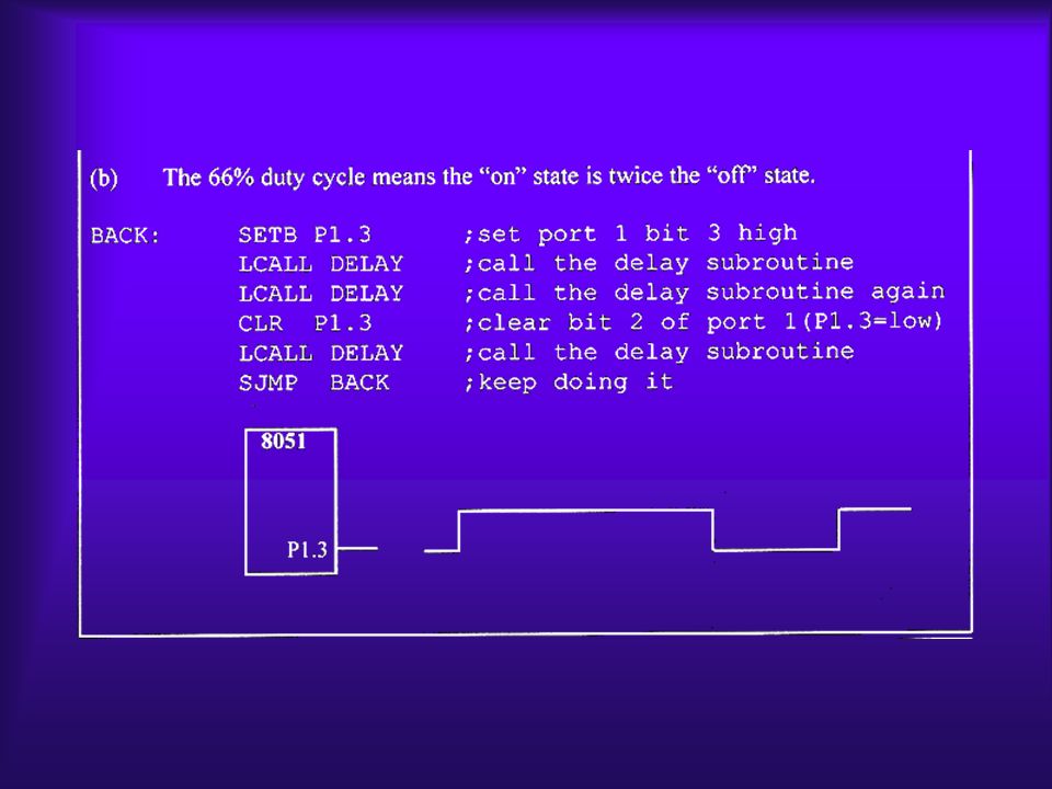
Single-bit instructions

75
I/O ports and bit-addressability The 8051 has four I/O ports, each of which is 8 bits

80
Checking an input bit JNB (jump if no bit) ; JB (jump if bit = 1)
 ; JB (jump if bit = 1)")
81
Registers and bit-addressability

83
Figure 8-2. Bits of the PSW Register

85
Bit-addressable RAM

88
Single-bit operations with CY

92
Instructions for reading input port READING INPUT PINS VS. PORT LATCH In Reading a port: 1.Read the status of the input pin 2.Read the internal latch of the output port

93
Reading latch for output port

Similar presentations


>")


