Download presentation
Presentation is loading. Please wait.

1
Team Dosen UMN Database Design Connolly Book Chapter 16-18

2
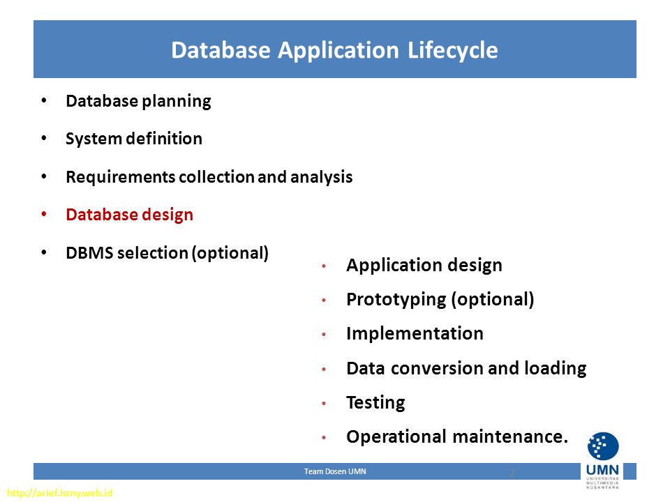
Team Dosen UMN Database Application Lifecycle 2 Database planning System definition Requirements collection and analysis Database design DBMS selection (optional) Application design Prototyping (optional) Implementation Data conversion and loading Testing Operational maintenance. http://arief.ismy.web.id
3
Team Dosen UMN Design Methodology Design Methodology is a structured approach that uses procedures, techniques, tools, and documentation aids to support and facilitate the process of design. Database Design Methodology has 3 phases: – Conceptual database design – Logical database design – Physical database design

4
Team Dosen UMN 3 Phases of Database Methodology Conceptual Database Design: The process of constructing a model of the data used in an enterprise, independent of all physical considerations. Logical Database Design: The process of constructing a model of the data used in an enterprise based on a specific data model (e.g. relational), but independent of a particular DBMS and other physical considerations. Physical database design: The process of producing a description of the implementation of the database on secondary storage; it describes the base relations, file organizations, and indexes design used to achieve efficient access to the data, and any associated integrity constraints and security measures.
, but independent of a particular DBMS and other physical considerations. Physical database design: The process of producing a description of the implementation of the database on secondary storage; it describes the base relations, file organizations, and indexes design used to achieve efficient access to the data, and any associated integrity constraints and security measures..")
5
Team Dosen UMN Critical Success Factors in Database Design Work interactively with the users as much as possible. Follow a structured methodology throughout the data modelling process. Employ a data-driven approach. Incorporate structural and integrity considerations into the data models. Combine conceptualization, normalization, and transaction validation techniques into the data modelling methodology. Use diagrams to represent as much of the data models as possible. Use a Database Design Language (DBDL) to represent additional data semantics. Build a data dictionary to supplement the data model diagrams. Be willing to repeat steps.
 to represent additional data semantics. Build a data dictionary to supplement the data model diagrams. Be willing to repeat steps..")
6
Team Dosen UMN Overview Database Design Methodology Conceptual Database Design Step 1 Build conceptual data model Logical Database Design Step 2 Build and validate logical data model Physical Database Design Step 3 Translate logical data model for target DBMS Step 4 Design file organizations and indexes Step 5 Design user views Step 6 Design security mechanisms Step 7 Consider the introduction of controlled redundancy Step 8 Monitor and tune the operational system

7
Team Dosen UMN Conceptual database design Step 1 Build conceptual data model – Step 1.1Identify entity types – Step 1.2Identify relationship types – Step 1.3Identify and associate attributes with entity or relationship types – Step 1.4Determine attribute domains – Step 1.5Determine candidate, primary, and alternate key attributes – Step 1.6Consider use of enhanced modeling concepts (optional step) – Step 1.7Check model for redundancy – Step 1.8Validate conceptual model against user transactions – Step 1.9Review conceptual data model with user
 – Step 1.7Check model for redundancy – Step 1.8Validate conceptual model against user transactions – Step 1.9Review conceptual data model with user")
8
Team Dosen UMN Logical database design for the relational model Step 2 Build and validate logical data model – Step 2.1 Derive relations for logical data model – Step 2.2 Validate relations using normalization – Step 2.3 Validate relations against user transactions – Step 2.4 Define integrity constraints – Step 2.5 Review logical data model with user – Step 2.6 Merge logical data models into global model (optional step) – Step 2.7 Check for future growth
 – Step 2.7 Check for future growth")
9
Team Dosen UMN Physical database design for relational database Step 3 Translate logical data model for target DBMS – Step 3.1 Design base relations – Step 3.2 Design representation of derived data – Step 3.3 Design general constraints Step 4 Design file organizations and indexes – Step 4.1 Analyze transactions – Step 4.2 Choose file organization – Step 4.3 Choose indexes – Step 4.4 Estimate disk space requirements Step 5 Design user views Step 6 Design security mechanisms Step 7 Consider the introduction of controlled redundancy Step 8 Monitor and tune the operational system

10
Team Dosen UMN Step 1 Build Conceptual Data To build a conceptual data model of the data requirements of the enterprise. – Model comprises entity types, relationship types, attributes and attribute domains, primary and alternate keys, and integrity constraints. Step 1.1 Identify entity types – To identify the required entity types. – Documentation:

11
Team Dosen UMN Step 1 Build Conceptual Data One method to find entities is by examining user requirements, that includes – Identify noun/noun phrases (Q: example of noun/noun phrases?) – Look for major objects (people, place, concept interest, etc). – Look for objects in their own right (i.e. Staff)
.")
12
Team Dosen UMN Step 1 Build Conceptual Data Step 1.2 Identify relationship types – To identify the important relationships that exist between the entity types.

13
Team Dosen UMN Step 1.2 Identify relationship types Documentation:

14
Team Dosen UMN Step 1 Build Conceptual Data Step 1.3 Identify and associate attributes with entity or relationship types – To associate attributes with the appropriate entity or relationship types and document the details of each attribute. Step 1.4 Determine attribute domains – To determine domains for the attributes in the data model and document the details of each domain. Documentation:

15
Team Dosen UMN Step 1 Build Conceptual Data Step 1.5 Determine candidate, primary, and alternate key attributes – To identify the candidate key(s) for each entity and if there is more than one candidate key, to choose one to be the primary key and the others as alternate keys. Documentation: ER diagram for Staff user views of DreamHome with primary keys added

16
Team Dosen UMN Step 1 Build Conceptual Data Step 1.6 Consider use of enhanced modeling concepts (optional step) – To consider the use of enhanced modeling concepts, such as specialization / generalization, aggregation, and composition. Documentation: Revised ER diagram for Staff user views of DreamHome with specialization / generalization

17
Team Dosen UMN Step 1 Build Conceptual Data Step 1.7 Check model for redundancy – To check for the presence of any redundancy in the model and to remove any that does exist. Example of removing a redundant relationship called Rents

18
Team Dosen UMN Step 1 Build Conceptual Data Step 1.8 Validate conceptual model against user transactions – To ensure that the conceptual model supports the required transactions. Using pathways to check that the conceptual model supports the user transactions

19
Team Dosen UMN Step 1 Build Conceptual Data Step1.9 Review conceptual data model with user – To review the conceptual data model with the user to ensure that the model is a ‘true’ representation of the data requirements of the enterprise.

20
Team Dosen UMN Conceptual database design Step 1 Build conceptual data model – Step 1.1Identify entity types – Step 1.2Identify relationship types – Step 1.3Identify and associate attributes with entity or relationship types – Step 1.4Determine attribute domains – Step 1.5Determine candidate, primary, and alternate key attributes – Step 1.6Consider use of enhanced modeling concepts (optional step) – Step 1.7Check model for redundancy – Step 1.8Validate conceptual model against user transactions – Step 1.9Review conceptual data model with user
 – Step 1.7Check model for redundancy – Step 1.8Validate conceptual model against user transactions – Step 1.9Review conceptual data model with user")
21
Team Dosen UMN Step 2 Build and Validate Logical Data Model To translate the conceptual data model into a logical data model and then to validate this model to check that it is structurally correct using normalization and supports the required transactions.

22
Team Dosen UMN Step 2 Build and Validate Logical Data Model Step 2.1 Derive relations for logical data model – To create relations for the logical data model to represent the entities, relationships, and attributes that have been identified.

23
Team Dosen UMN (1)Strong entity types For each strong entity in the data model: create a relation that includes all the simple attributes of that entity. For composite attributes, include only the constituent simple attributes. Step 2.1 Derive relations for logical data model Staff(staffNo,Name,lName,position,sex,DOB) Primary Key staffNo
 Primary Key staffNo.")
24
Team Dosen UMN Step 2.1 Derive relations for logical data model (2)Weak entity types – For each weak entity in the data model, create a relation that includes all the simple attributes of that entity. The primary key of a weak entity is partially or fully derived from each owner entity and so the identification of the primary key of a weak entity cannot be made until after all the relationships with the owner entities have been mapped. Preference(prefType,maxRent) Primary Key None at present
 Primary Key None at present.")
25
Team Dosen UMN Step 2.1 Derive relations for logical data model (3)One-to-many (1:*) binary relationship types – For each 1:* binary relationship, the entity on the ‘one side’ of the relationship is designated as the parent entity and the entity on the ‘many side’ is designated as the child entity. To represent this relationship, post a copy of the primary key attribute(s) of parent entity into the relation representing the child entity, to act as a foreign key. Staff(staffNo,Name,lName,position,sex,DOB) Primary Key staffNo Client(clientNo,fName,lName,telNo,eMail,staffNo) Primary Key clientNo Alternative Key eMail Foreign Key staffNo references Staff(staffNo)
 of parent entity into the relation representing the child entity, to act as a foreign key. Staff(staffNo,Name,lName,position,sex,DOB) Primary Key staffNo Client(clientNo,fName,lName,telNo, ,staffNo) Primary Key clientNo Alternative Key Foreign Key staffNo references Staff(staffNo).")
26
Team Dosen UMN Step 2.1 Derive relations for logical data model (4)One-to-one (1:1) binary relationship types – Creating relations to represent a 1:1 relationship is more complex as the cardinality cannot be used to identify the parent and child entities in a relationship. Instead, the participation constraints are used to decide whether it is best to represent the relationship by combining the entities involved into one relation or by creating two relations and posting a copy of the primary key from one relation to the other. – Consider the following (a) mandatory participation on both sides of 1:1 relationship; (b) mandatory participation on one side of 1:1 relationship; (c) optional participation on both sides of 1:1 relationship.
 mandatory participation on both sides of 1:1 relationship; (b) mandatory participation on one side of 1:1 relationship; (c) optional participation on both sides of 1:1 relationship..")
27
Team Dosen UMN Step 2.1 Derive relations for logical data model (a)Mandatory participation on both sides of 1:1 relationship Combine entities involved into one relation and choose one of the primary keys of original entities to be primary key of the new relation, while the other (if one exists) is used as an alternate key. Client(clientNo,fName,lName,telNo,eMail,staffNo) Primary Key clientNo Alternative Key eMail Foreign Key staffNo references Staff(staffNo) Preference(prefType,maxRent) Primary Key None at present Client(clientNo,fName,lName,telNo,eMail,prefType,maxRent,staffNo) Primary Key clientNo Alternative Key eMail Foreign Key staffNo references Staff(staffNo) BEFORE AFTER
 Primary Key clientNo Alternative Key Foreign Key staffNo references Staff(staffNo) Preference(prefType,maxRent) Primary Key None at present Client(clientNo,fName,lName,telNo, ,prefType,maxRent,staffNo) Primary Key clientNo Alternative Key Foreign Key staffNo references Staff(staffNo) BEFORE AFTER.")
28
Team Dosen UMN Step 2.1 Derive relations for logical data model (b) Mandatory participation on one side of a 1:1 relationship Identify parent and child entities using participation constraints. Entity with optional participation in relationship is designated as parent entity, and entity with mandatory participation is designated as child entity. A copy of primary key of the parent entity is placed in the relation representing the child entity. If the relationship has one or more attributes, these attributes should follow the posting of the primary key to the child relation. Client(clientNo,fName,lName,telNo,eMail,staffNo) Primary Key clientNo Alternative Key eMail Foreign Key staffNo references Staff(staffNo) Preference(prefType,maxRent) Primary Key None at present Preference(clientNo,prefType,maxRent) Primary Key cleintNo Foreign Key clientNo references Client(clientNo) Client(clientNo,fName,lName,telNo,eMail,staffNo) Primary Key clientNo Alternative Key eMail Foreign Key staffNo references Staff(staffNo) BEFORE AFTER
 Primary Key clientNo Alternative Key Foreign Key staffNo references Staff(staffNo) Preference(prefType,maxRent) Primary Key None at present Preference(clientNo,prefType,maxRent) Primary Key cleintNo Foreign Key clientNo references Client(clientNo) Client(clientNo,fName,lName,telNo, ,staffNo) Primary Key clientNo Alternative Key Foreign Key staffNo references Staff(staffNo) BEFORE AFTER.")
29
Team Dosen UMN Step 2.1 Derive relations for logical data model (c) Optional participation on both sides of a 1:1 relationship In this case, the designation of the parent and child entities is arbitrary unless we can find out more about the relationship that can help a decision to be made one way or the other. For example Staff uses Car. Both sides are optional participation. Majority cars are used by Staffs but not all. We can make Staff as the parent ad Car as the child. Post a copy of primary key of Staff into Car.

30
Team Dosen UMN Step 2.1 Derive relations for logical data model (5) One-to-one (1:1) recursive relationships For a 1:1 recursive relationship, follow the rules for participation as described above for a 1:1 relationship. mandatory participation on both sides, represent the recursive relationship as a single relation with two copies of the primary key. The copies of the primary keys act as foreign keys and have to be renamed to indicate the purpose of each in the relation. mandatory participation on only one side, option to create a single relation with two copies of the primary key, or to create a new relation to represent the relationship. The new relation would only have two attributes, both copies of the primary key. As before, the copies of the primary keys act as foreign keys and have to be renamed to indicate the purpose of each in the relation. optional participation on both sides, again create a new relation as described above.

31
Team Dosen UMN Step 2 Build and Validate Logical Data Model (6) Superclass/subclass relationship types – Identify superclass entity as parent entity and subclass entity as the child entity. There are various options on how to represent such a relationship as one or more relations. – The selection of the most appropriate option is dependent on a number of factors such as the disjointness and participation constraints on the superclass/subclass relationship, whether the subclasses are involved in distinct relationships, and the number of participants in the superclass/subclass relationship. Participation Constraint Disjoint ConstraintRelations Required MandatoryNondisjoint {And}Single Relation: One or more discriminators to distiguish the type of each tuple OptionalNondisjoint {And}Two Relations: One as superclass and other as subclass MandatoryDisjoint {Or}Many Relations: one relation for each combined superclass/cubclass OptionalDisjoint {Or}Many Relations: one relation for superclass and one for each subclass

32
Team Dosen UMN Representation of superclass / subclass relationship based on participation and disjointness

33
Team Dosen UMN Step 2 Build and Validate Logical Data Model (7) Many-to-many (*:*) binary relationship types – Create a relation to represent the relationship and include any attributes that are part of the relationship. We post a copy of the primary key attribute(s) of the entities that participate in the relationship into the new relation, to act as foreign keys. These foreign keys will also form the primary key of the new relation, possibly in combination with some of the attributes of the relationship. Client(clientNo,fName,lName,telNo,eMail,staffNo) Primary Key clientNo Alternative Key eMail Foreign Key staffNo references Staff(staffNo) PropertyForRent(propertyNo, street, city, postcode, type, rooms, rent) Primary Key propertyNo Viewing(clientNo,propertyNo,dateview,comment Primary Key clientNo, propertyNo Foreign Key clientNo references Client(clientNo) Foreign Key propertyNo references PropertyForRent(propertyNo)
 of the entities that participate in the relationship into the new relation, to act as foreign keys. These foreign keys will also form the primary key of the new relation, possibly in combination with some of the attributes of the relationship. Client(clientNo,fName,lName,telNo, ,staffNo) Primary Key clientNo Alternative Key Foreign Key staffNo references Staff(staffNo) PropertyForRent(propertyNo, street, city, postcode, type, rooms, rent) Primary Key propertyNo Viewing(clientNo,propertyNo,dateview,comment Primary Key clientNo, propertyNo Foreign Key clientNo references Client(clientNo) Foreign Key propertyNo references PropertyForRent(propertyNo).")
34
Team Dosen UMN Step 2.1 Derive relations for logical data model (8) Complex relationship types – Create a relation to represent the relationship and include any attributes that are part of the relationship. Post a copy of the primary key attribute(s) of the entities that participate in the complex relationship into the new relation, to act as foreign keys. Any foreign keys that represent a ‘many’ relationship (for example, 1..*, 0..*) generally will also form the primary key of this new relation, possibly in combination with some of the attributes of the relationship. Client(clientNo,fName,lName,telNo,eMail,staffNo) Primary Key clientNo Alternative Key eMail Foreign Key staffNo references Staff(staffNo) Staff(staffNo,Name,lName,position,sex,DOB, supervisorStaffNo) Primary Key staffNo Foreign key supervisorStaffNo references Staff(staffNo) Branch(branchNo, street, city, postcode) Primary Key branchNo Registration(clientNo, branchNo, staffNo, dateJoined Primary Key clientNo, branchNo Foreign Key branchNo references Branch(branchNo) Foreign Key clientNo references Client(clientNo) Foreign Key staffNo references Staff(staffNo)
 of the entities that participate in the complex relationship into the new relation, to act as foreign keys. Any foreign keys that represent a ‘many’ relationship (for example, 1..*, 0..*) generally will also form the primary key of this new relation, possibly in combination with some of the attributes of the relationship. Client(clientNo,fName,lName,telNo, ,staffNo) Primary Key clientNo Alternative Key Foreign Key staffNo references Staff(staffNo) Staff(staffNo,Name,lName,position,sex,DOB, supervisorStaffNo) Primary Key staffNo Foreign key supervisorStaffNo references Staff(staffNo) Branch(branchNo, street, city, postcode) Primary Key branchNo Registration(clientNo, branchNo, staffNo, dateJoined Primary Key clientNo, branchNo Foreign Key branchNo references Branch(branchNo) Foreign Key clientNo references Client(clientNo) Foreign Key staffNo references Staff(staffNo).")
35
Team Dosen UMN Step 2.1 Derive relations for logical data model (9)Multi-valued attributes – Create a new relation to represent multi-valued attribute and include primary key of entity in new relation, to act as a foreign key. Unless the multi-valued attribute is itself an alternate key of the entity, the primary key of the new relation is the combination of the multi-valued attribute and the primary key of the entity. Branch(branchNo, street, city, postcode) Primary Key branchNo Telephone(telNo, branchNo) Primary Key telNo Foreign Key branchNo references Branch(branchNo)
 Primary Key branchNo Telephone(telNo, branchNo) Primary Key telNo Foreign Key branchNo references Branch(branchNo).")
36
Team Dosen UMN Step 2.2 Validate relations using normalization The objective is to validate the relations in the logical data model using normalization. The Normalization process includes 1NF, 2NF, 3NF (at least 3NF is recommended)
.")
37
Team Dosen UMN Step 2.3 Validate relations against user transactions To ensure that the relations in the logical data model support the required transactions.

38
Team Dosen UMN Step 2.4 Check integrity constraints To check integrity constraints are represented in the logical data model. This includes identifying: Required data Attribute domain constraints Multiplicity Entity integrity Referential integrity General constraints

39
Team Dosen UMN Referential integrity constraints for relations in Staff user views of DreamHome

40
Team Dosen UMN Step 2.5 Review logical data model with user To review the logical data model with the users to ensure that they consider the model to be a true representation of the data requirements of the enterprise.

41
Team Dosen UMN Step 2.6 Merge logical data models into global Model (optional step) To merge logical data models into a single global logical data model that represents all user views of a database. This activity includes: – Step 2.6.1 Merge local logical data models into global model – Step 2.6.2 Validate global logical data model – Step 2.6.3 Review global logical data model with users.

42
Team Dosen UMN Step 2.6 Merge logical data models into global Model (optional) Step 2.6.1 Merge local logical data models into global model Tasks typically includes: (1) Review the names and contents of entities/relations and their candidate keys. (2) Review the names and contents of relationships/foreign keys. (3) Merge entities/relations from the local data models (4) Include (without merging) entities/relations unique to each local data model (5) Merge relationships/foreign keys from the local data models. (6) Include (without merging) relationships/foreign keys unique to each local data model. (7) Check for missing entities/relations and relationships/foreign keys. (8) Check foreign keys. (9) Check Integrity Constraints. (10) Draw the global ER/relation diagram (11) Update the documentation.
 Review the names and contents of relationships/foreign keys. (3) Merge entities/relations from the local data models (4) Include (without merging) entities/relations unique to each local data model (5) Merge relationships/foreign keys from the local data models. (6) Include (without merging) relationships/foreign keys unique to each local data model. (7) Check for missing entities/relations and relationships/foreign keys. (8) Check foreign keys. (9) Check Integrity Constraints. (10) Draw the global ER/relation diagram (11) Update the documentation..")
43
Team Dosen UMN Step 2.6 Merge logical data models into global Model (optional) Step 2.6.2 Validate global logical data model To validate the relations created from the global logical data model using the technique of normalization and to ensure they support the required transactions, if necessary. Step 2.6.3 Review global logical data model with users. To review the global logical data model with the users to ensure that they consider the model to be a true representation of the data requirements of an enterprise.

44
Team Dosen UMN Relations for the Branch user views of DreamHome

45
Team Dosen UMN Relations that represent the global logical data model for DreamHome

46
Team Dosen UMN Global relation diagram for DreamHome

47
Team Dosen UMN Step 2.7. Check The Future Growth To determine whether there are any significant changes likely in the foreseeable future and to assess whether the logical data model can accommodate these changes.

48
Team Dosen UMN Summary of how to map entities and relationships to relations

Similar presentations


 Matakuliah: T0206-Sistem Basisdata Tahun: 2005 Versi: 1.0/0.0.>")


 Transparencies.>")


 Implementation Data conversion.>")
