Download presentation
Presentation is loading. Please wait.

1
DEVICES AND COMMUNICATION BUSES FOR DEVICES NETWORK

2
Bus Communication for networking
Each specific I/O device may be connected to other using specific interfaces, for example, with I/O device for example, LCD controller, keyboard controller and print controller. Bus communication simplifies the number of connections and provides a common way (protocol) of connecting different or same type of I/O devices
 of connecting different or same type of I/O devices.")
3
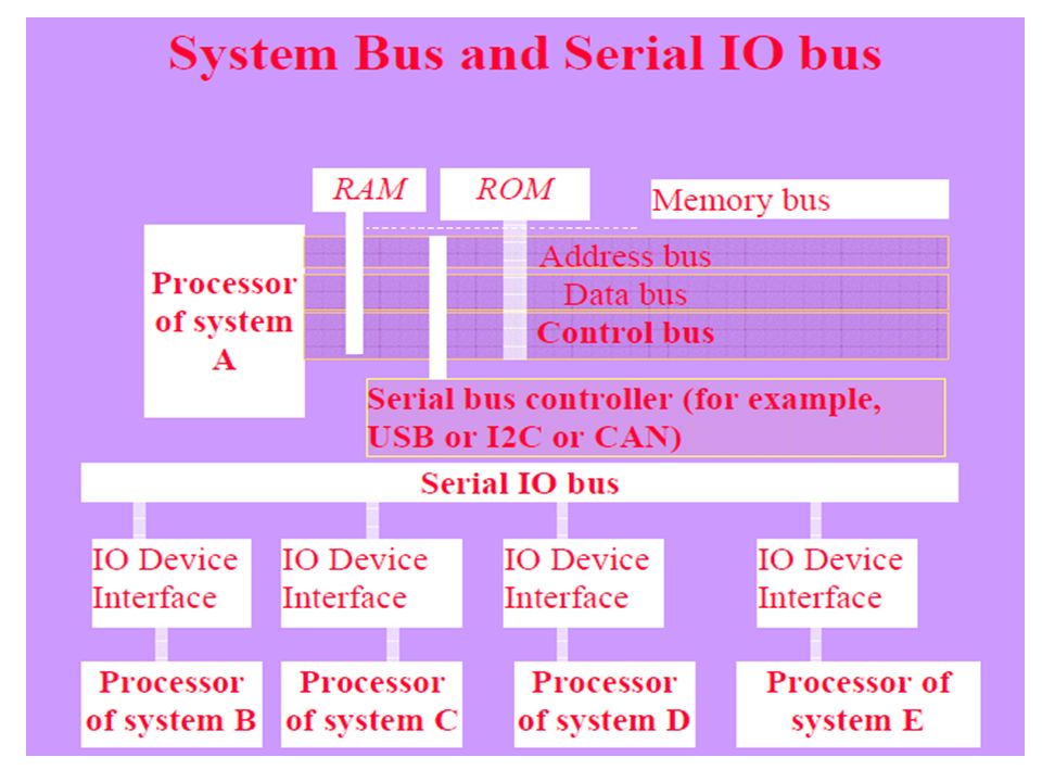
IO Bus Any device that is compatible with a system's I/O bus can be added to the system (assuming an appropriate device driver program is available), and a device that is compatible with a particular I/O bus can be integrated into any system that uses that type of bus. I/O devices communicate with the processor through an I/O bus, which is separate from the memory bus that the processor uses to communicate with the memory system.
, and a device that is compatible with a particular I/O bus can be integrated into any system that uses that type of bus. I/O devices communicate with the processor through an I/O bus, which is separate from the memory bus that the processor uses to communicate with the memory system.")
5
Embedded systems Networking
Embedded systems connected internally on same IC or systems at very short, short and long distances can be networked using a type of the I/O buses- CAN, I2C, USB, PCI, …

6
IO Bus for Networking vs. direct connections
Use of I/O bus, as opposed to direct connections between the processor and each I/O device, very flexible, allowing a system to support many different I/O devices depending on the needs of its users and allowing users to change the I/O devices that are attached to a system as their needs change.

7
Main disadvantage of an I/O bus
A bus has a fixed bandwidth that must be shared by all of the devices on the bus. Even worse, electrical constraints (wire length and transmission line effects) cause buses to have less bandwidth than using the same number of wires to connect just two devices. Essentially, there is a trade-off between interface simplicity and bandwidth. Example A bus has bandwidth of 2 Mb/s (can be used to transfer 2 Mb data in one s. If 10 devices are connected, the 2 Mb/s is shared between the networked systems
 cause buses to have less bandwidth than using the same number of wires to connect just two devices. Essentially, there is a trade-off between interface simplicity and bandwidth. Example. A bus has bandwidth of 2 Mb/s (can be used to transfer 2 Mb data in one s. If 10 devices are connected, the 2 Mb/s is shared between the networked systems.")
8
Serial Bus A serial bus has very few lines and the number of lines as per the protocol. A wide range of I/O devices without having to implement a specific interface for each I/O device. When the I/O devices in the distributed embedded systems are networked at long distances of 25 cm and above, all can communicate through a common serial bus.

9
Internet or intranet Using Internet or intranet, a computer or controller or embedded system IO device interface and globally network with computers and a wide range of devices in the systems Parallel Bus Using a parallel I/O bus allows a computer or controller or embedded system to interface with number of internal systems at very short distances without having to implement a specific interface for each I/O device.

10
Short distances Wireless Bus protocol
Up to 100 m using wireless personal area network (WPAN) WPAN protocol without having to implement a specific wireless interface for each I/O device Allows a handheld computer or controller or embedded system I/O device to interface and network with number of handheld system I/O devices of other handheld
 WPAN protocol without having to implement a specific wireless interface for each I/O device. Allows a handheld computer or controller or embedded system I/O device to interface and network with number of handheld system I/O devices of other handheld.")
11
SERIAL BUS COMMUNICATION PROTOCOLS – I2C

12
Interconnecting number of device circuits
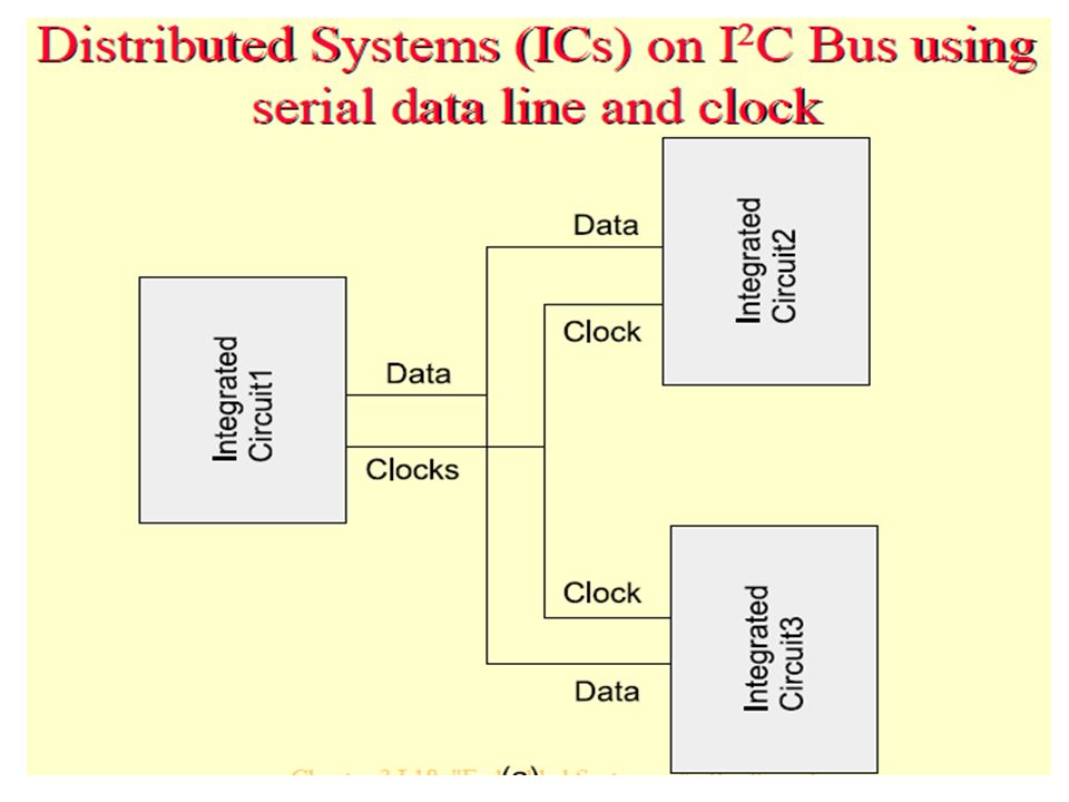
Assume flash memory, touch screen, ICs for measuring temperatures and ICs for measuring pressures at a number of processes in a plant. ICs mutually network through a common synchronous serial bus I2C An 'Inter Integrated Circuit' (I2C) bus, a popular bus for these circuits.
 bus, a popular bus for these circuits.")
13
Synchronous Serial Bus Communication for n/wing
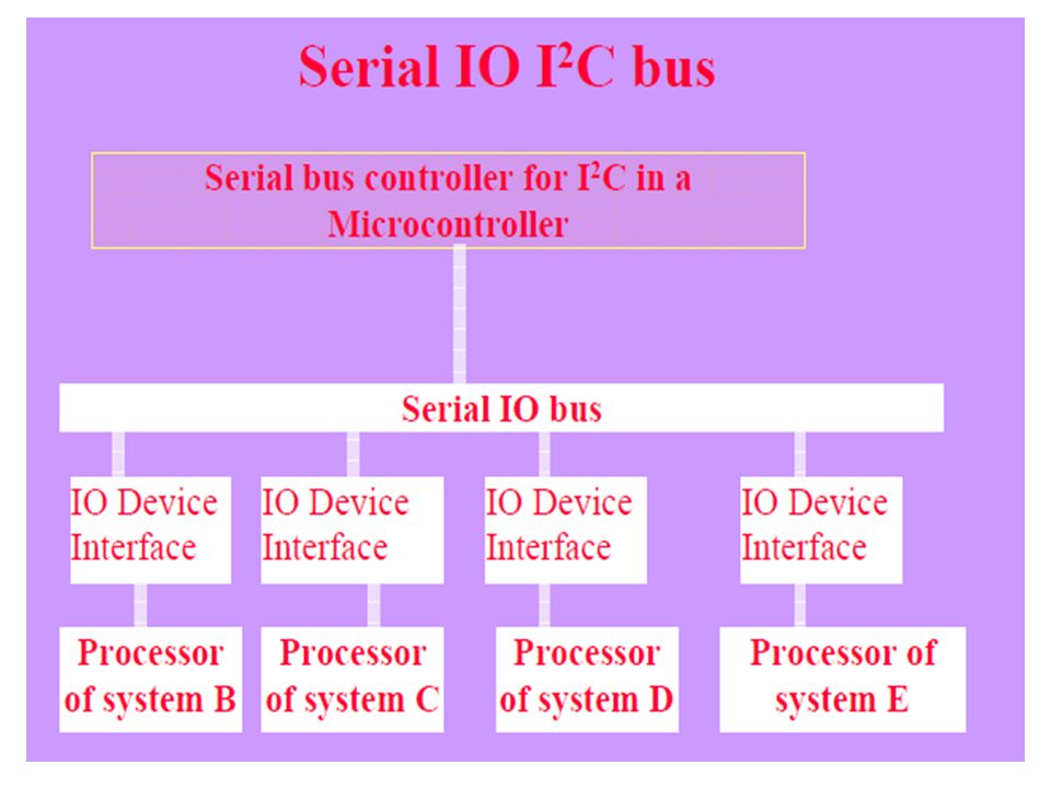
Each specific I/O synchronous serial device may be connected to other using specific interfaces, for example, with I/O device using I2C controller I2C Bus communication− use of only simplifies the number of connections and provides a common way (protocol) of connecting different or same type of I/O devices using synchronous serial communication
 of connecting different or same type of I/O devices using synchronous serial communication.")
14
IO I2C Bus Any device that is compatible with a I2C bus can be added to the system (assuming an appropriate device driver program is available), and a I2C device can be integrated into any system that uses that I2C bus.
, and a I2C device can be integrated into any system that uses that I2C bus.")
16
Originally developed at Philips Semiconductors
Synchronous Serial Communication 400 kbps up to 2 m and 100 kbps for longer distances Three I2C standards 1. Industrial 100 kbps I2C, kbps SM I2C, kbps I2C

18
I2C Bus The Bus has two lines that carry its signals— one line is for the clock and one is for bi-directional data. There is a standard protocol for the I2C bus. Device Addresses and Master in the I2C bus Each device has a 7-bit address using which the data transfers take place. Master can address 127 other slaves at an instance. Master has at a processing element functioning as bus controller or a microcontroller with I2C (Inter Integrated Circuit) bus interface circuit.
 bus interface circuit.")
19
Slaves and Masters in the I2C bus
Each slave can also optionally has I2C (Inter Integrated Circuit) bus controller and processing element. Number of masters can be connected on the bus. However, at an instance, master is one, which initiates a data transfer on SDA (serial data) line and which transmits the SCL (serial clock) pulses. From master, a data frame has fields beginning from start bit.
 bus controller and processing element. Number of masters can be connected on the bus. However, at an instance, master is one, which initiates a data transfer on SDA (serial data) line and which transmits the SCL (serial clock) pulses. From master, a data frame has fields beginning from start bit.")
21
Synchronous Serial Bus Fields and its length
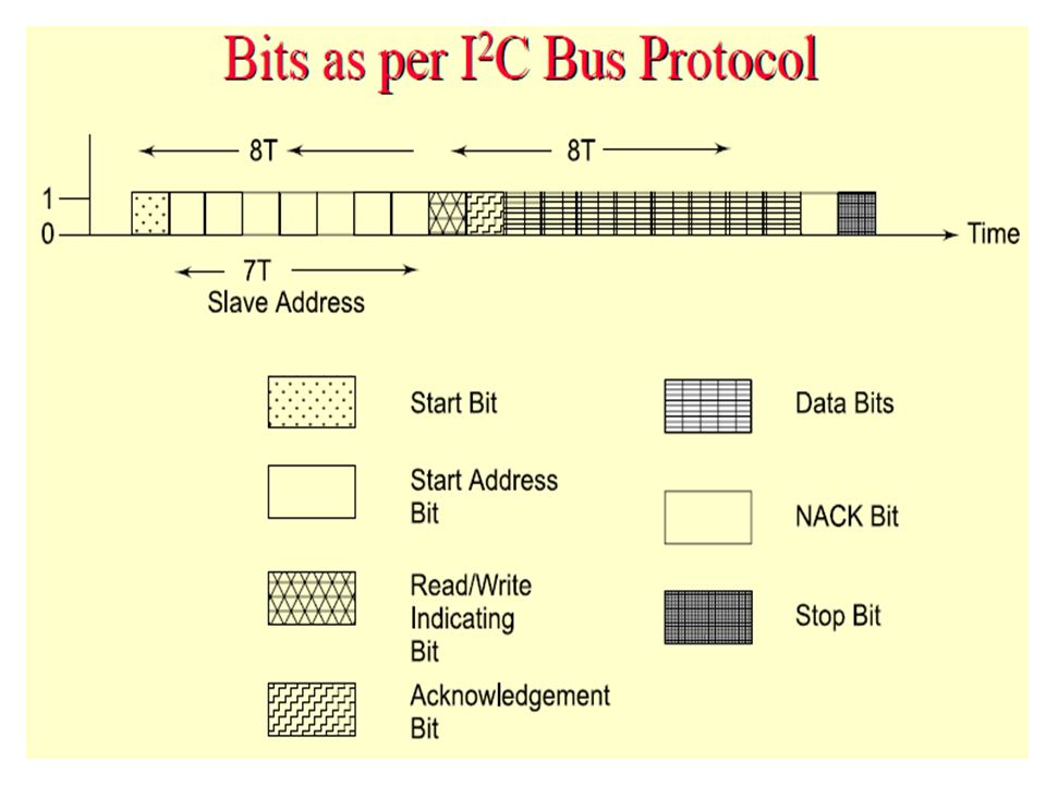
First field of 1 bit─ Start bit similar to one in an UART Second field of 7 bits─ address field. It defines the slave address, which is being sent the data frame (of many bytes) by the master Third field of 1 control bit─ defines whether a read or write cycle is in progress Fourth field of 1 control bit─ defines whether is the present data is an acknowledgment (from slave)
 by the master. Third field of 1 control bit─ defines whether a read or write cycle is in progress. Fourth field of 1 control bit─ defines whether is the present data is an acknowledgment (from slave)")
22
Synchronous Serial Bus Fields and its length
Fifth field of 8 bits─ I2C device data byte Sixth field of 1-bit - bit NACK (negative acknowledgement) from the receiver. If active then acknowledgment after a transfer is not needed from the slave, else acknowledgement is expected from the slave Seventh field of 1 bit ─ stop bit like in an UART
 from the receiver. If active then acknowledgment after a transfer is not needed from the slave, else acknowledgement is expected from the slave. Seventh field of 1 bit ─ stop bit like in an UART.")
23
Disadvantage of I2C bus Time taken by algorithm in the hardware that analyzes the bits through I2C in case the slave hardware does not provide for the hardware that supports it. Certain ICs support the protocol and certain do not. Open collector drivers at the master need a pull-up resistance of 2.2 K on each line.

24
SERIAL BUS COMMUNICATION PROTOCOLS – CAN

25
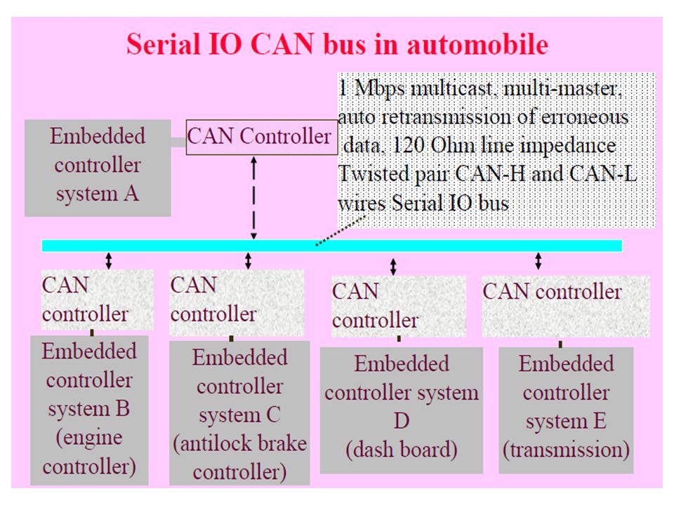
Serial Communication Distributed Control Area Network (CAN) Bus
Distributed Control Area Network example - a network of embedded systems in automobile

26
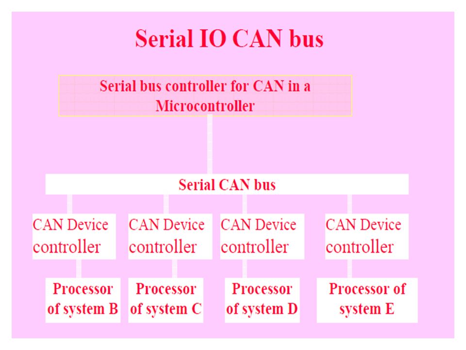
CAN Serial Bus Communication for Networking
CAN-bus line usually interconnects to a CAN controller between line and host at the node. It gives the input and gets output between the physical and data link layers at the host node. The CAN controller has a BIU (bus interface unit consisting of buffer and driver), protocol controller, status-cum-control registers, receiver-buffer and message objects. These units connect the host node through the host interface circuit
, protocol controller, status-cum-control registers, receiver-buffer and message objects. These units connect the host node through the host interface circuit.")
29
Three standards: 33 kbps CAN, 110 kbps Fault Tolerant CAN, 1 Mbps High Speed CAN CAN protocol There is a CAN controller between the CAN line and the host node. CAN controller ─BIU (Bus Interface Unit) consisting of a buffer and driver Method for arbitration─ CSMA/AMP (Carrier Sense Multiple Access with Arbitration on Message Priority basis)
 consisting of a buffer and driver. Method for arbitration─ CSMA/AMP (Carrier Sense Multiple Access with Arbitration on Message Priority basis)")
30
Each Distributed Node Uses:
Twisted Pair Connection up to 40 m – for bi-directional data Line, which pulls to Logic 1 through a resistor between the line and + 4.5V to +12V. : Line Idle state Logic 1 (Recessive state) Uses a buffer gate between an input pin and the CAN line Detects Input Presence at the CAN line pulled down to dominant (active) state logic 0 (ground ~ 0V) by a sender to the CAN line Uses a current driver between the output pin and CAN line and pulls line down to dominant (active) state logic 0 (ground ~ 0V) when sending to the CAN line
 Uses a buffer gate between an input pin and the CAN line. Detects Input Presence at the CAN line pulled down to dominant (active) state logic 0 (ground ~ 0V) by a sender to the CAN line. Uses a current driver between the output pin and CAN line and pulls line down to dominant (active) state logic 0 (ground ~ 0V) when sending to the CAN line.")
31
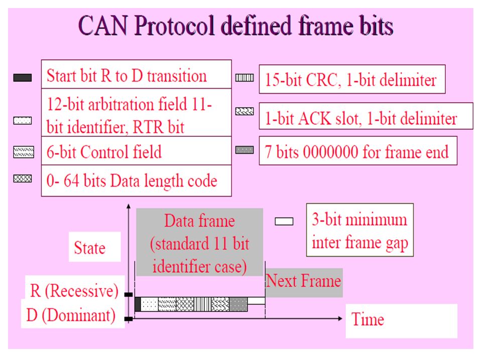
Protocol defined start bit followed by six fields of frame bits
Data frame starts after first detecting that dominant state is not present at the CAN line with logic 1 (R state) to 0 (D state transition) for one serial bit interval After start bit, six fields starting from arbitration field and ends with seven logic 0s end-field 3-bit minimum inter frame gap before next start bit (R→ D transition) occurs
 to 0 (D state transition) for one serial bit interval. After start bit, six fields starting from arbitration field and ends with seven logic 0s end-field. 3-bit minimum inter frame gap before next start bit (R→ D transition) occurs.")
33
Protocol defined First field in frame bits
First field of 12 bits ─'arbitration field. 11-bit destination address and RTR bit (Remote Transmission Request) Destination device address specified in an 11-bit sub-field and whether the data byte being sent is a data for the device or a request to the device in 1-bit sub-field. Maximum 211 devices can connect a CAN controller in case of 11-bit address field standard
 Destination device address specified in an 11-bit sub-field and whether the data byte being sent is a data for the device or a request to the device in 1-bit sub-field. Maximum 211 devices can connect a CAN controller in case of 11-bit address field standard.")
34
11-bit address standard CAN
Identifies the device to which data is being sent or request is being made. When RTR bit is at '1', it means this packet is for the device at destination address. If this bit is at '0' (dominant state) it means, this packet is a request for the data from the device.
 it means, this packet is a request for the data from the device.")
35
Protocol defined frame bits Second field
Second field of 6 bits─ control field. The first bit is for the identifier’s extension. The second bit is always '1'. The last 4 bits specify code for data length Protocol defined frame bits Third field Third field of 0 to 64 bits─ Its length depends on the data length code in the control field.

36
Protocol defined frame bits Fourth field
Fourth field (third if data field has no bit present) of 16 bits─ CRC (Cyclic Redundancy Check) bits. The receiver node uses it to detect the errors, if any, during the transmission
 of 16 bits─ CRC (Cyclic Redundancy Check) bits. The receiver node uses it to detect the errors, if any, during the transmission.")
37
Protocol defined frame bits Fifth field
Fifth field of 2 bits─ First bit 'ACK slot‘ ACK = '1' and receiver sends back '0' in this slot when the receiver detects an error in the reception. Sender after sensing '0' in the ACK slot, generally retransmits the data frame. Second bit 'ACK delimiter' bit. It signals the end of ACK field. If the transmitting node does not receive any acknowledgement of data frame within a specified time slot, it should retransmit.

38
Protocol defined frame bits Sixth field
Sixth field of 7-bits ─ end- of- theframe specification and has seven '0's.

Similar presentations


![Setha Pan-ngum. History of CAN [1] It was created in mid-1980s for automotive applications by Robert Bosch. Design goal was to make automobiles more reliable,](/13/3602303/big_thumb.jpg "Setha Pan-ngum. History of CAN [1] It was created in mid-1980s for automotive applications by Robert Bosch. Design goal was to make automobiles more reliable,>")


>")

