Download presentation
Presentation is loading. Please wait.

2
Chapter 5: Superposition of waves

3
Superposition principle applies to any linear system At a given place and time, the net response caused by two or more stimuli is the sum of the responses which would have been caused by each stimulus individually.

4
in a linear world, disturbances coexist without causing further disturbance

5
then the linear combination where a and b are constants is also a solution. Superposition of waves If 1 and 2 are solutions to the wave equation,

6
Superposition of light waves 1 2 -in general, must consider orientation of vectors (Chapter 7—next week) -today, we’ll treat electric fields as scalars -strictly valid only when individual E vectors are parallel -good approximation for nearly parallel E vectors -also works for unpolarized light
 -today, we’ll treat electric fields as scalars -strictly valid only when individual E vectors are parallel -good approximation for nearly parallel E vectors -also works for unpolarized light")
7
Light side of life

8
Nonlinear optics is another story for another course, perhaps

9
What happens when two plane waves overlap?

10
Superposition of waves of same frequency propagation distance (measured from reference plane) initial phase (at t =0)
 initial phase (at t =0)")
11
Superposition of waves of same frequency simplify by intoducing constant phases: thus At point P, phase difference is hence the resultant electric field at P is.

12
“in step” Superposition of waves of same frequency “out of step” constructive interference destructive interference

15
In between the extremes: constructivedestructive notice the amplitudes can vary; it’s all about the phase general superposition

16
General case of superposition Simplify with phasors whereand Expressed in complex form:

17
Phasors, not phasers

18
Phasor diagrams projection onto x -axis magnitude angle clock analogy: -time is a line -but time has repeating nature -use circular, rotating representation to track time phasors: -represent harmonic motion -complex plane representation -use to track waves -simplifies computational manipulations

19
Phasors in motion http://resonanceswavesandfields.blogspot.com/2007/08/phasors.html

20
Phasor diagrams complex space representation; vector addition from law of cosines we get the amplitude of the resultant field:

21
Phasor diagrams taking the tangent we get the phase of the resultant field

22
Works for 2 waves, works for N waves -harmonic waves -same frequency

23
hence as Two important cases for waves of equal amplitude and frequency randomly phasedcoherent phase differences random hence as in phase; all i are equal

24
Light from a light bulb is very complicated! 1 It has many colors (it’s white), so we have to add waves of many different values of (and hence k -magnitudes). 2It’s not a point source, so for each color, we have to add waves with many different k directions. 3Even for a single color along one direction, many different atoms are emitting light with random relative phases. Lightbulb
, so we have to add waves of many different values of (and hence k -magnitudes). 2It’s not a point source, so for each color, we have to add waves with many different k directions. 3Even for a single color along one direction, many different atoms are emitting light with random relative phases. Lightbulb.")
25
Coherent light: - strong - uni-directional - irradiance N 2 Incoherent light: - relatively weak - omni-directional - irradiance N Coherent vs. Incoherent light

26
Coherent fixed phase relationship between the electric field values at different locations or at different times Partially coherent some (although not perfect) correlation between phase values Incoherent no correlation between electric field values at different times or locations 1 0 Coherence is a continuum more on coherence next week
 correlation between phase values Incoherent no correlation between electric field values at different times or locations 1 0 Coherence is a continuum more on coherence next week")
28
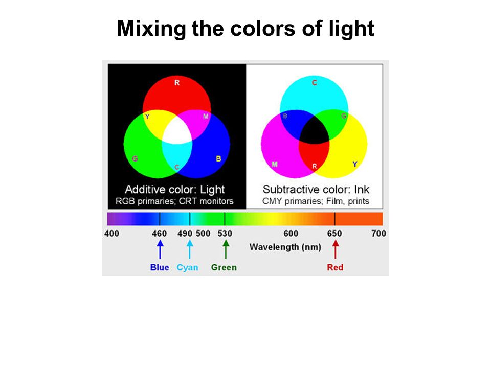
Mixing the colors of light

29
How to make a pulse of light

30
Time Intensity 1. Single frequency Time Intensity 2. Multi-frequency Statistical phase relation amongst different frequencies I N Time Intensity 3. Modelocked Constant or linear phase amongst frequencies I N 2 T = 2L/c Laser operating regimes

31
Standing waves - occur when wave exists in both forward and reverse directions - if phase shift = , standing wave is created - when A ( x ) = 0, E R =0 for all t ; these points are called nodes - displacemeent at nodes is always zero A(x)A(x)
 = 0, E R =0 for all t ; these points are called nodes - displacemeent at nodes is always zero A(x)A(x)")
32
Standing wave anatomy - nodes occur when A ( x ) = 0 - A ( x ) = 0 when sin kx = 0, or kx = m (for m = 0, ±1, ±2,...) - since k = 2 x = ½ m - E R has maxima when cos t = ±1 - hence, peaks occur at t = ½ mT ( T is the period) where
 = 0 - A ( x ) = 0 when sin kx = 0, or kx = m (for m = 0, ±1, ±2,...) - since k = 2 x = ½ m - E R has maxima when cos t = ±1 - hence, peaks occur at t = ½ mT ( T is the period) where")
33
Standing waves in action http://www.youtube.com/watch?v=0M21_zCo6UM light water sound http://www.youtube.com/watch?v=EQPMhwuYMy4

34
Superposition of waves of different frequency pp gg kpkp kgkg

35
Beats Here, two cosine waves, with p >> g

36
Beats beat frequency: The product of the two waves is depicted as: Phasor representation: http://www.compadre.org/osp/items/detail.cfm?ID=8174http://www.compadre.org/osp/items/detail.cfm?ID=8174

37
2 frequencies4 frequencies 16 frequencies Many frequencies Acoustic analogy

38
Here, phase velocity = group velocity (the medium is non-dispersive). In a dispersive medium, the phase velocity ≠ group velocity. Phase and group velocity phase velocity: group velocity: envelopemoves with group velocity carrier wave moves with phase velocity

39
non-dispersive mediumdispersive medium Superposition and dispersion of a waveform made of 100 cosines with different frequencies

40
http://www.youtube.com/watch?v=umrp1tIBY8Q And the beat goes on

41
You are encouraged to solve all problems in the textbook (Pedrotti 3 ). The following may be covered in the werkcollege on 22 September 2010: Chapter 5: 2, 6, 8, 9, 14, 18 Exercises (not part of your homework)
.")
Similar presentations


 Ltd. Constructive and destructive interference Mathematical approach Mathematical approach 9.8 Interference of water waves.>")


>")


 What determines the tones of strings on a guitar?>")
>")


