Download presentation
Presentation is loading. Please wait.

1
Electrical and Optical Cables Installation at P5 What When How H. Breuker 20-7-04

2
Installation Tasks Cable Channels and Patch Panel 1 Cable Installation up to PP1 Cable Installation from PP1 to Balconies and the Service Cavern (USC) Cable Installation from UXC to USC Test Procedures to be defined CMS rule : Cables delivered for Installation must be fully connectorized !
 Cable Installation from UXC to USC Test Procedures to be defined CMS rule : Cables delivered for Installation must be fully connectorized !")
3
Installation up to PP1 Optical Fiber Ribbons (4500) Aluminium MSC (1200) 2 Types TOB 1 Type TIB / TID Control Power Cables (200) 1 Type TOB 1 Type TIB / TID (Remember : TEC has its PP1 inside the Bulkheads)
 Aluminium MSC (1200) 2 Types TOB 1 Type TIB / TID Control Power Cables (200) 1 Type TOB 1 Type TIB / TID (Remember : TEC has its PP1 inside the Bulkheads)")
4
“Main” Installation Electrical Cables (MSC or LIC) up to Balconies (2000, average Length 40 meters) Control Power Cables up to Balconies (350, average Length 40 meters) Optical Fiber Cables up to FED/FEC racks in USC (560, average Length 50 meters)
 up to Balconies (2000, average Length 40 meters) Control Power Cables up to Balconies (350, average Length 40 meters) Optical Fiber Cables up to FED/FEC racks in USC (560, average Length 50 meters)")
8
Optical Ribbons and Cables (FV) Opt. Cables from PP1 to USC : about 4 weeks with 4 Operators under “Supervision” (before TK arrival at P5 ?!) Installation into PP1 : with Inspection and Cleaning, 2 Operators, 1-2 weeks ? Ribbons from TK to PP1: 2 Operators per End, 2-4 weeks ? Connection at PP1: with Inspection and Cleaning, 2 Operators, 2-4 weeks ? Link Reflectometry Test and Connection at FED/FEC : 6- 8 Operators, 4 Ref. Stations, 4-8 weeks
 Installation into PP1 : with Inspection and Cleaning, 2 Operators, 1-2 weeks . Ribbons from TK to PP1: 2 Operators per End, 2-4 weeks . Connection at PP1: with Inspection and Cleaning, 2 Operators, 2-4 weeks . Link Reflectometry Test and Connection at FED/FEC : 6- 8 Operators, 4 Ref. Stations, 4-8 weeks.")
11
“Additional” Cables Thermal Screen Power Cables (64) Thermal Screen Sensor Cables Alignment (TK Internal) Cables and Fibers Alignment (Link System) Cables and Fibers Heater Cables for Cable Channels (128) Pixel Electrical Cables (112) Pixel Optical Cables (36)
 Thermal Screen Sensor Cables Alignment (TK Internal) Cables and Fibers Alignment (Link System) Cables and Fibers Heater Cables for Cable Channels (128) Pixel Electrical Cables (112) Pixel Optical Cables (36)")
12
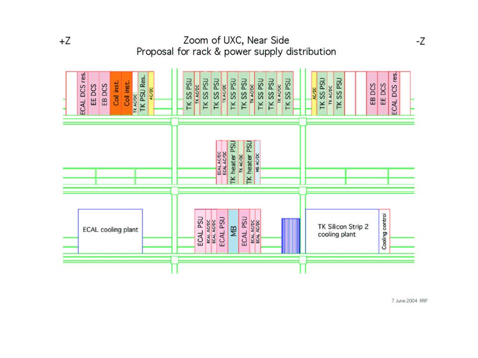
Cables between UXC and USC With the Decision to place the PSM’s in 120 Crates on the Balconies much reduced (proposed by R. Hammarstrom 1995) ! Power and Control of AC-DC Converters : 120 + 40 (gen. CMS Infrastructure, not on TK) Ambient Sensor Cables (120) Interlock Signal Cables (120) Debug / PSU Status Display Cables (120) SY1527 Control Cables (20)
 . Power and Control of AC-DC Converters : (gen. CMS Infrastructure, not on TK) Ambient Sensor Cables (120) Interlock Signal Cables (120) Debug / PSU Status Display Cables (120) SY1527 Control Cables (20).")
13
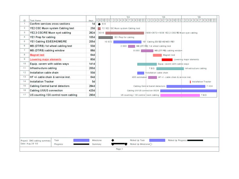
When ? CMS Assembly Schedule V34 Underground phase : Sept / Oct 06 and Dec / first half Jan 07 (cabling starts after arrival of TK at P5 ?!) G. Faber’ s Proposal (TCM March 8 2004) to start TK cabling on the + Z side 6 – 8 month’s before the arrival of TK at P5 First half of 2006 ! (Finish by end 2006)
 G. Faber’ s Proposal (TCM March ) to start TK cabling on the + Z side 6 – 8 month’s before the arrival of TK at P5 First half of (Finish by end 2006).")
15
How ? Estimate in Collaboration with CMS Integration Team and presented at (TCM Oct. 01) : Cabling between TK and PP1 about 2 Manyears (with available space for 4 People per end) Cabling and pipe installation outside the coil (32 channels per detector end and a total of 640 meters of channel) estimated at 15 Manyears Proposal G. Faber : Cabling of Central Barrel Detectors to be done by a Team of 11 People plus “Supervisor”. More than 1 Shift / day ? More people ?
 : Cabling between TK and PP1 about 2 Manyears (with available space for 4 People per end) Cabling and pipe installation outside the coil (32 channels per detector end and a total of 640 meters of channel) estimated at 15 Manyears Proposal G. Faber : Cabling of Central Barrel Detectors to be done by a Team of 11 People plus Supervisor . More than 1 Shift / day . More people .")
Similar presentations


 Brief Review Cost and Effort Estimate.>")
 Introduction 2.) Installation scenario 3.) SE schedule, manpower, cost estimates 4.) EE.>")


