Download presentation
Presentation is loading. Please wait.

2
Wiring the Control Box Battery Conductor(s) Resistor
 Resistor")
3
Wiring the Control Box Battery Conductors Resistor

4
Wiring the Control Box -Current has 1 path -Voltage is divided up to each resistor -Current is the same through each resistor -Current breaks up along multiple paths -Voltage across each resistor is the same -Current is divided up to the resistors SeriesParallel

5
Wiring the Control Box Series Parallel 12 V 3 V 12 V

6
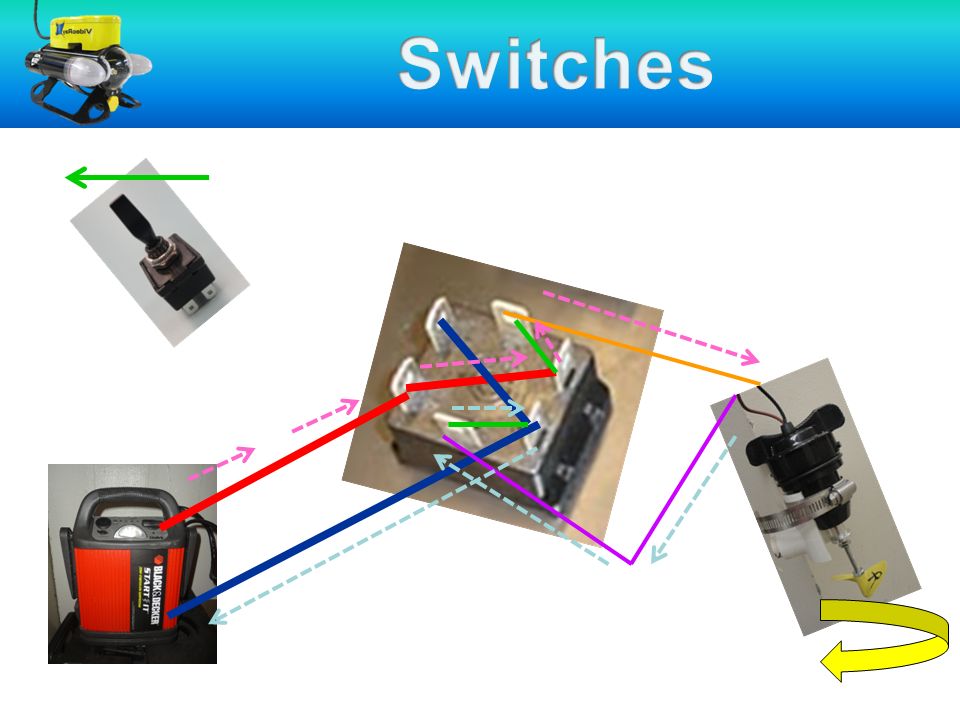
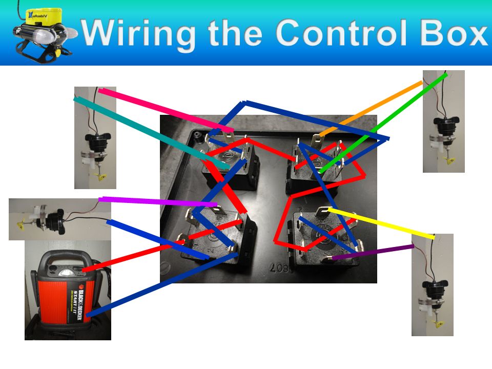
Wiring the Control Box Wires from tether: –8 wires coming into control box –2 wires for each switch (+/-) Wires from battery –2 wires coming into box –Connected in parallel to each switch 4 switches Box
 Wires from battery –2 wires coming into box –Connected in parallel to each switch 4 switches Box")
7
Wiring the Control Box

11
Get out your colored pencils and control box diagrams!

12
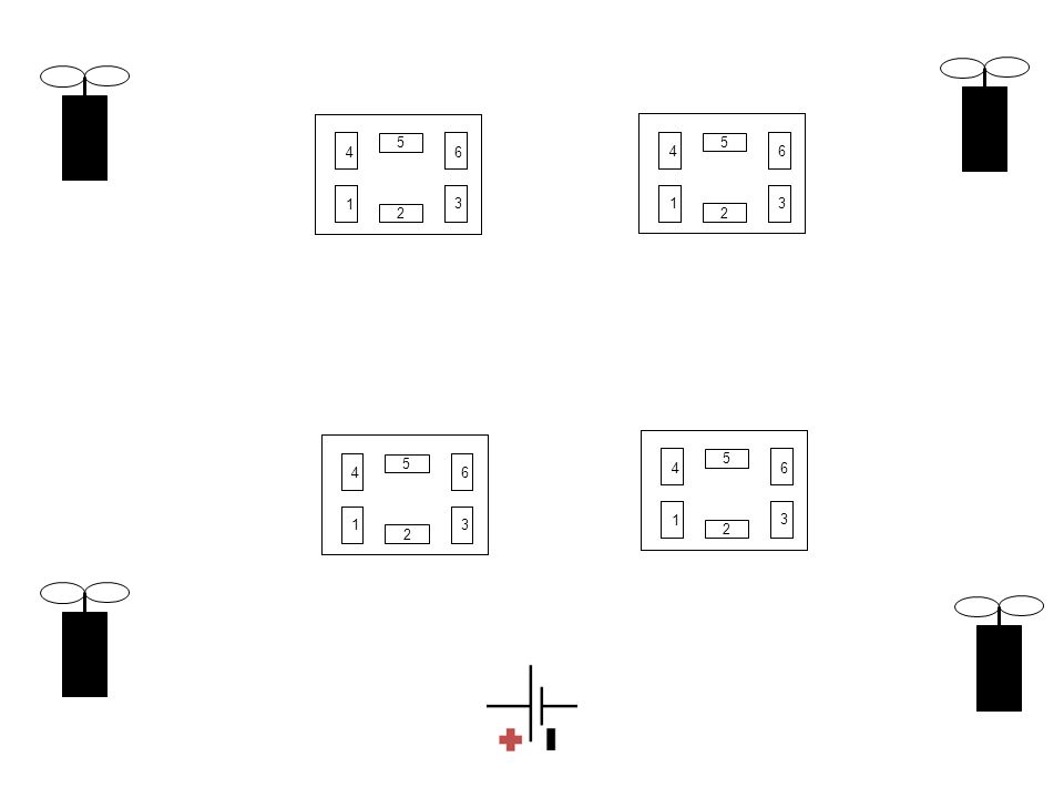
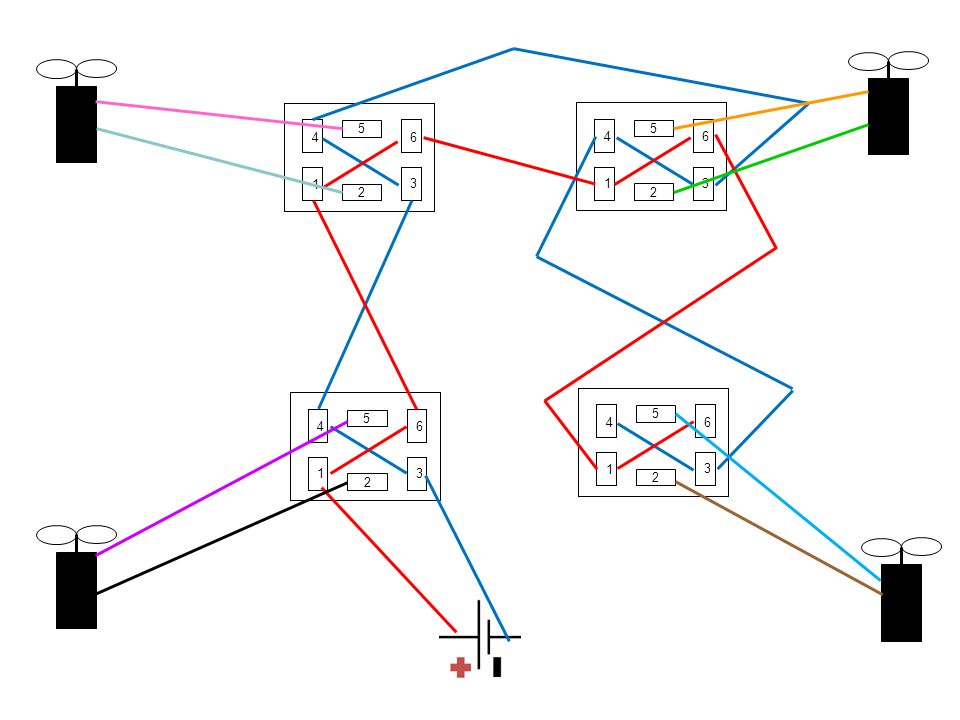
1 2 3 4 5 6 1 2 3 4 5 6 1 2 3 4 5 6 1 2 3 4 5 6
13
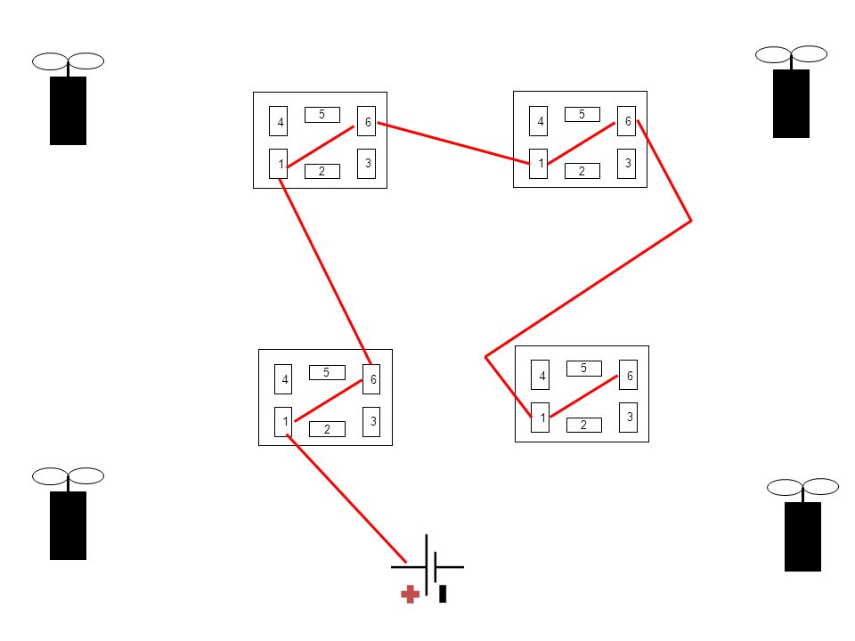
1 2 3 4 5 6 1 2 3 4 5 6 1 2 3 4 5 6 1 2 3 4 5 6
14
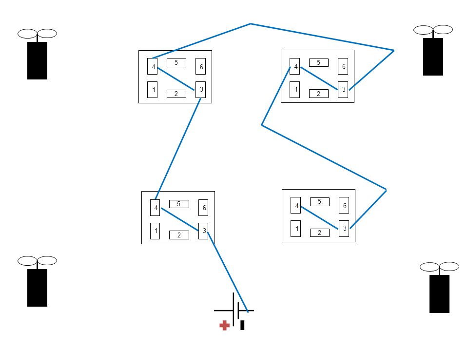
1 2 3 4 5 6 1 2 3 4 5 6 1 2 3 4 5 6 1 2 3 4 5 6
15
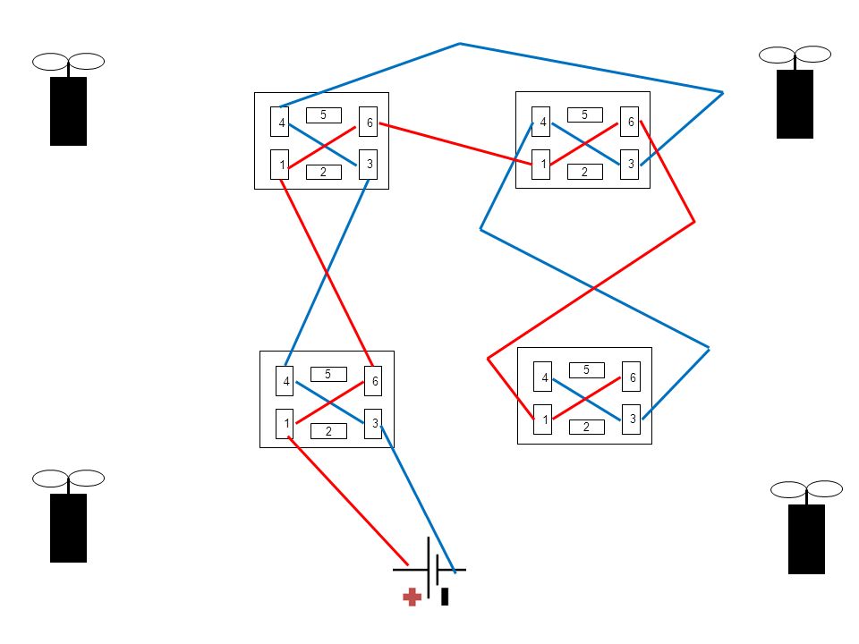
1 2 3 4 5 6 1 2 3 4 5 6 1 2 3 4 5 6 1 2 3 4 5 6
16
1 2 3 4 5 6 1 2 3 4 5 6 1 2 3 4 5 6 1 2 3 4 5 6
17
Wiring the Control Box 1 2 3 4 5 6 7 8

18
Parallel circuit 1 2 3 4 5 6 7 8

19
Wiring the Control Box Parallel circuit

20
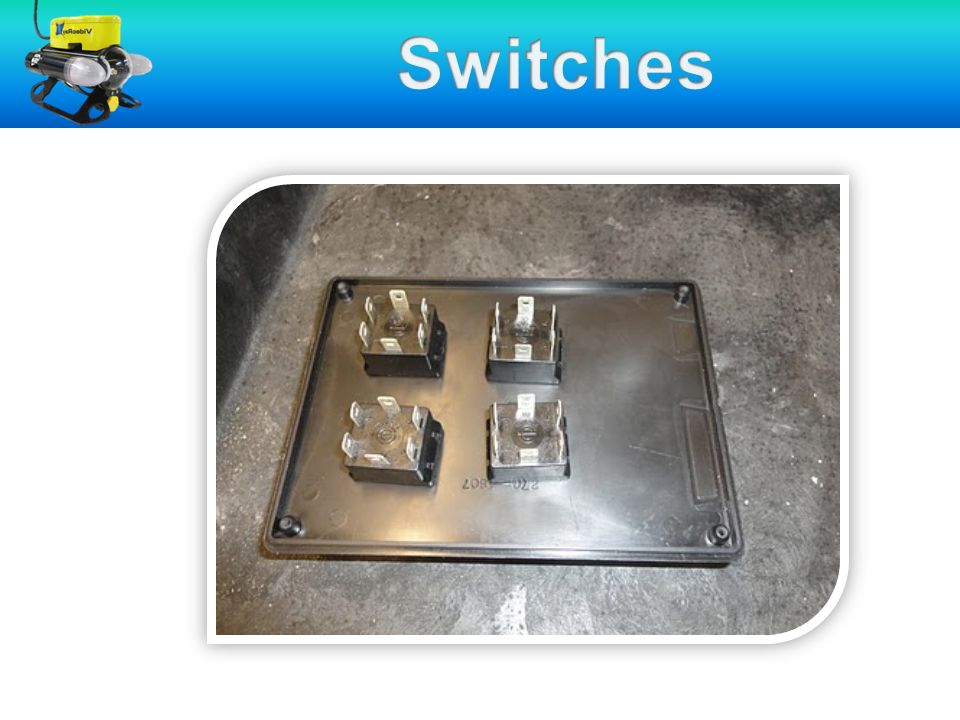
Wiring the Control Box

22
Stripping Wires Trying “wiring” your control box using string

23
Stripping Wires Use strippers for stripping plastic and exposing the wire as indicated in the essentials presentation.

24
Crimping Once the wire is firmly crimped, secure with electrical tape. 8 spades are needed to connect your red wires (same for the black set) To crimp the wires line them up next to each other and gently twist into metal ring until you can see both wires at other end. Use the crimping part of your red wire cutter/crimper. Make sure that you squeeze the metal ring and not just the plastic.
 To crimp the wires line them up next to each other and gently twist into metal ring until you can see both wires at other end. Use the crimping part of your red wire cutter/crimper. Make sure that you squeeze the metal ring and not just the plastic..")
25
Wiring the Control Box Measure distance between contacts. Cut 8 red wires and 8 black wires. Wire 1 has to be long enough to go through control box to the battery 8 1 2 3 4 5 6 7

26
Wiring the Control Box Once you have crimped together both your black and red wires you can attach the spades to the contacts.

27
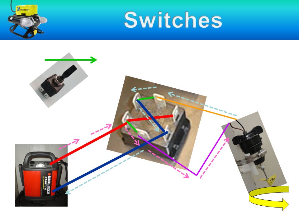
Wiring the Control Box Attaching the propellers Use 8 of the blue spades Use the same stripping and crimping technique Note which color wires go to each switch/propeller

28
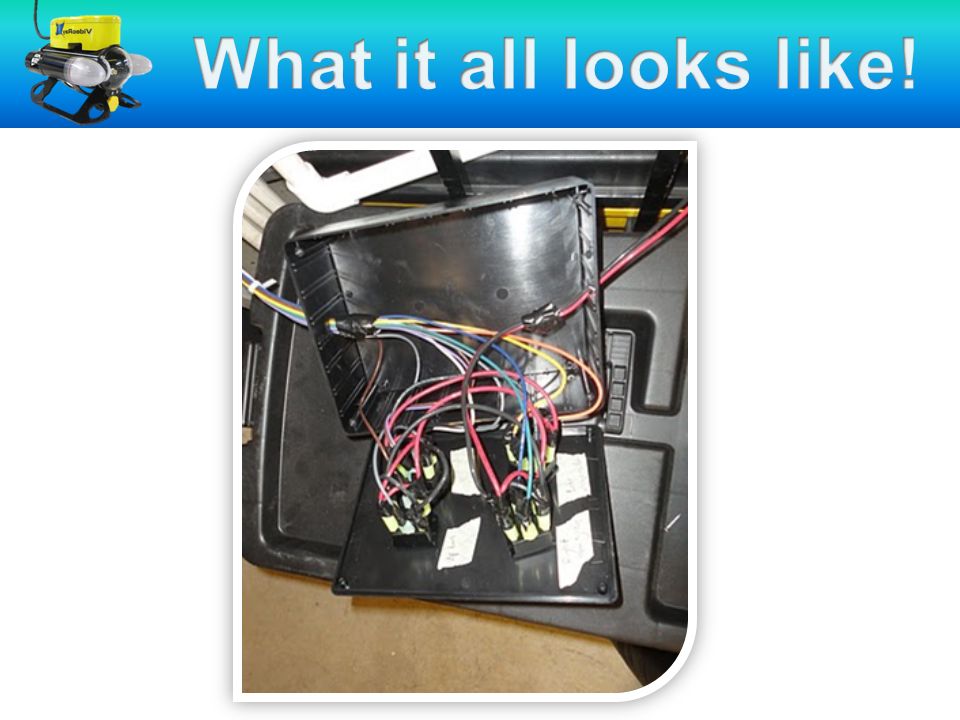
Wiring the Control Box Wires from a motor Wires from battery source

29
Wiring the Control Box

31
Control Box Helpful Tips: –Label the switches (inside and outside the box) as up/down, right, and left –Write down which color wires connect to which motor on the ROV –Connect all the wires together to the spades first, then plug the spades into the switches –Draw a diagram of which color wires connect where on the switches. If anything falls out, then it can easily be reconnected. –If a motor is turning the opposite direction desired, swap the 2 colored wires to opposite sides.

32
Wiring the Control Box Control Box with your Club: 2 nd and 3 rd year teachers: –What activities have your tried with your students? –Other tips?

Similar presentations
 national clean energy goals is to put one million.>")


 1 Perf Board 3Ceramic Resistors (4 5W) 39 V connectors 1 White wire 1.>")


>")


