Download presentation
Presentation is loading. Please wait.

1
An Introduction to Sazeh Negar 6

2
Main Features of Sazeh Negar
Automatic beam to column connection design Bolted connections (New) Spliced beam connections (New) Base plate advanced design Automatic bracing gusset plate design Advanced section designer Overall structural check Creating structural drawings Shear wall drawings for steel structures (New) 3D model export to Tekla Structures (New)
 Spliced beam connections (New) Base plate advanced design. Automatic bracing gusset plate design. Advanced section designer. Overall structural check. Creating structural drawings. Shear wall drawings for steel structures (New) 3D model export to Tekla Structures (New)")
4
Beam to Column Connections
Calculating the maximum bearing strength in moment connections in accordance with seismic provisions (plastic hinge) Calculating the maximum bearing strength of simple and moment connections using the ETABS and SAP analyses or using the maximum capacity of beam. Automatic design of different types of simple and moment connections. Capability to assign the designed connections to beam ends all over the structure and viewing the connection details in 3d environment.
 Calculating the maximum bearing strength of simple and moment connections using the ETABS and SAP analyses or using the maximum capacity of beam. Automatic design of different types of simple and moment connections. Capability to assign the designed connections to beam ends all over the structure and viewing the connection details in 3d environment.")
5
Bolted Connections Connection design in accordance with AISC
Applying pre-tensioning Tension critical path analysis for bolts ASTM, DIN and EN bolt standards A307, A325, A490, DIN 4014, DIN 6914 User-defined bolt groups Calculation book.

6
Sample Bolted Connection Drawings

7
Spliced Beam Connection Design
Design and check spliced beam connection (with longitudinal plates). Capability to choose different types of connectors for splice plate connection to other components (Workshop weld, site weld and site bolt). Force calculation at splice plate location in accordance with AISC. Optional inner flange plates. Calculations book
. Capability to choose different types of connectors for splice plate connection to other components (Workshop weld, site weld and site bolt). Force calculation at splice plate location in accordance with AISC. Optional inner flange plates. Calculations book.")
8
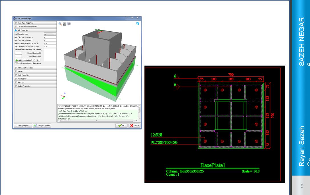
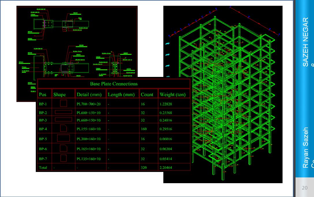
Base plate advanced design
Calculating the stress below the base plate and determining the neutral axis using complex math formulae for ordinary and biaxial bending. Capability to define bolts at any position and calculating the tensile stress at each bolt independently. Capability to model stiffeners at default and user-defined positions. Measuring the base plate and stiffeners dimensions and thickness and weld design of all base plate connections. Capability to design corner base plates with user-defined eccentricity. Designing base plates suitable for different types of column profiles (IPE, IPB, twin profiles, built up sections, …) Creating detailed structural calculation book covering all calculations and formulae.
 Creating detailed structural calculation book covering all calculations and formulae.")
10
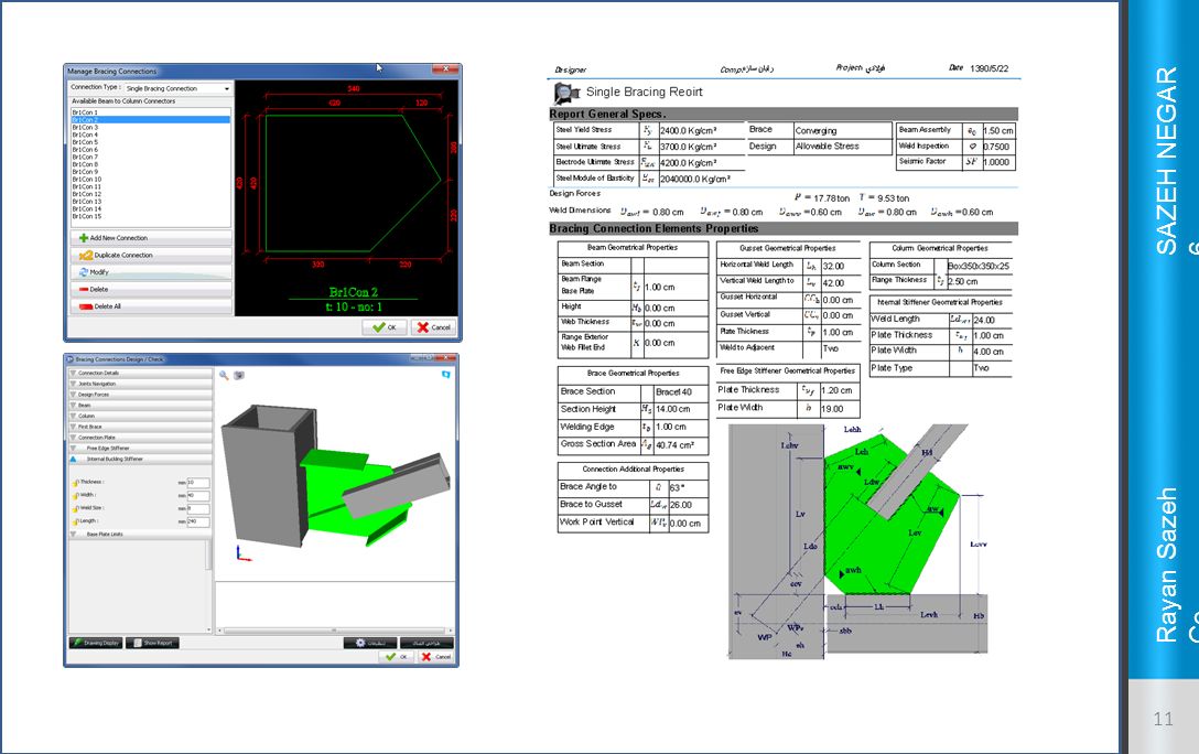
Automatic bracing gusset plate design
Gusset plate check and design in accordance with AISC seismic provisions and checking Whitmore tensions. Different types of bracings such as single profile, twin profile, X bracing, inverted V and multi bracings. Grouping and numbering gusset plates according to bracing angle, profile and connection type. Capability to design gussets using ETABS and SAP2000 analysis results or bracing profile capacity or user-defined loads. 3d display of designed gusset plates. Detailed structural calculation book

12
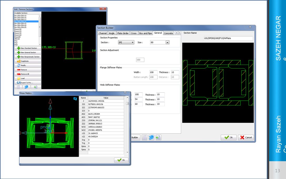
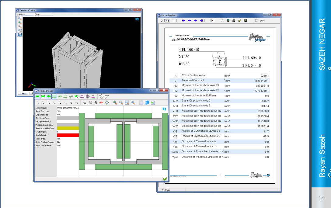
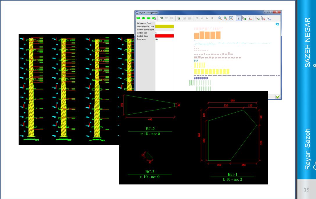
Advanced section designer
Flexible and user friendly user interface Capability to create castellated IPE (CPE), castellated INP (CNP), built up sections, channels, angles, IPE, INP and … . Capability to create custom and irregular sections in Advanced Section Designer. Calculating section static properties. Capability to export defined sections as *.pro files so they can be used in SAP2000 and ETABS. Printable section static data report and 3d display of sections.
, castellated INP (CNP), built up sections, channels, angles, IPE, INP and … . Capability to create custom and irregular sections in Advanced Section Designer. Calculating section static properties. Capability to export defined sections as *.pro files so they can be used in SAP2000 and ETABS. Printable section static data report and 3d display of sections.")
15
Overall structural check
Calculating structure stability index. Checking column base uplift. Checking structure lateral displacement. Checking distance between structure mass center and rigidity center. Irregularity control on structure plan. Creating SAFE import file using ETABS and SAP2000 analysis results

16
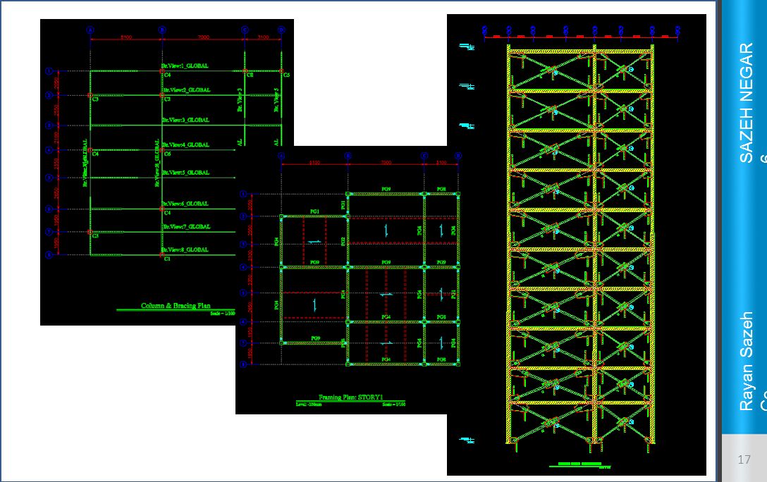
Creating structural drawings
Columns and bracings plan. Base plates plan. Beams plans drawings Secondary beams direction Additional plates Beam to column connection type Elevation and side views.

18
Structural drawings - continued
Four standard column views Bracing details Connection details Workshop drawings for connection parts Material lists Independent drawing editor Export drawings as DWG or DXF Automatic drawing sheets aligning

21
Shear wall drawings for steel structures
Capability to define different types of shear walls. Capability to define several different horizontal and vertical reinforcement bar groups. Capability to define reinforcement bars and ties in boundary elements with custom hooks. Modeling ordinary and concrete buried steel columns. Wall sections, views and plan drawing. Capability to draw wall connection to foundation and floors.

23
3D model export to Tekla Structures
Quick and precise conversion of ETABS project to Tekla Structures model. Capability to recognize General and SD sections. Automatic assembling of parts. Capability to export selected objects only.

25
Step by Step Sample Project
Here we are going to take a quick look at the steps required to go through to create a Sazeh Negar project, design different kinds of connections and finally create the structural drawings and reports.

26
Step1: Making Mdb files in SAP2000 or ETABS
When the analysis and design is finalized in ETABS or SAP2000 we should make the Mdb files needed in Sazeh Negar.

27
Step 2: Importing Mdb file
In Sazeh Negar we should import the Mdb file created in the step 1. Sazeh Negar will check if all the data is correctly inserted in the Mdb file.

28
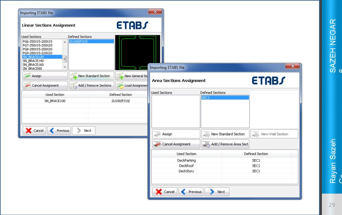
Step 3. Mapping the profiles
In this step we should map the profiles existing in Mdb files to new profiles in Sazeh Negar by means of section designer. Linear elements Wall and deck sections Sazeh Negar can retrieve the sections defined using ETABS section designer by means of e2k file.

30
Step 4. Finalizing Import
In this step user can enter the project information such as address, title, owner, structure designer and … The last thing to check is load case properties. Sazeh Negar will show the list of load cases retrieved from Mdb and user can add/remove selected ones.

32
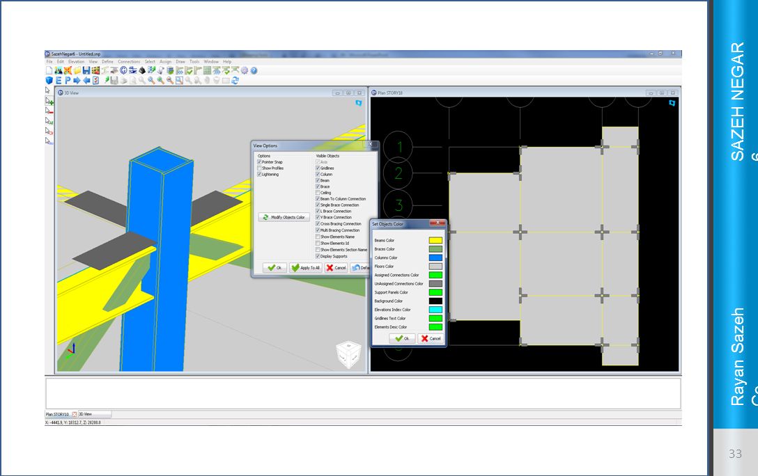
Step 5. User Interface Standard dual window display
Real profiles display Elements color customization Changing beams alignment Main menu and toolbar

34
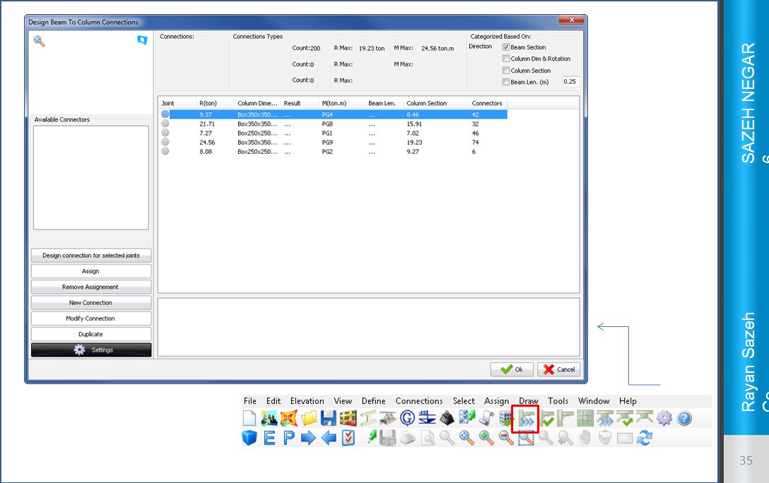
Step 6. Beam to column connections
Here user may take advantage of any of following tools: Auto Connection tool: detects and sorts all the existing beam-columns joints in the project. Single joint connection design: user manually selects the joint and goes through design and assignment process or he may design a connection using user-defined loads independent from the project joints.

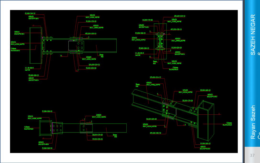
36
Sazeh Negar checks every single user modification to connection and logs the conflicts and warnings below the 3d view. The design will be final when all the connection parts become green and warning messages are disappeared.

38
Step 7. Bracing gusset plates
Both automatic and manual design are available. The general procedure is almost the same as beam to column connection design. User may design new connections, modify existing connections or remove assignment and delete the connections.

39
Filtering options List of all bracing connections

40
Step 8. Design results check
Now that all beam to column connections and gusset plates are designed, user may ask Sazeh Negar to check all the connections individually against their own real positions and configuration. Sazeh Negar reports the probable problems at the bottom of the main window below main views. User may click on each line of the report to zoom into the selected connection and examine the problem more closely.

42
Step 9. Base plates Filtering and sorting is automatically done using the columns profile. User may enter eccentricity for each base plate individually. The precise amount of stress is calculated for all the four corners of base plate using biaxial stress calculation. Tension in each anchor bolt is precisely measured.

44
Step 10. Drawings and Material Lists
User may change all the colors, layers, fonts, text styles and scales used in drawings. Options for creating different types of drawings are categorized in separate sections in Settings windows. User may choose to create all the drawings in one single phase or create drawings of specific type. User can plot the drawings directly from Sazeh Negar. User may edit the drawings using the Drawing Editor before exporting or plotting the drawings.

45
Sazeh Negar Settings window

46
Some of the drawing settings

Similar presentations


 BEAM- COLUMNS SHEAR / CONC. LOADS>")


 CE 408 ( 2 – 3 – 3 ) Semester 062>")


