Download presentation
Presentation is loading. Please wait.

1
PCI 6th Edition Connection Design

2
Presentation Outline Structural Steel Design Limit State Weld Analysis
Strut – Tie Analysis for Concrete Corbels Anchor Bolts Connection Examples

3
Changes New method to design headed studs (Headed Concrete Anchors - HCA) Revised welding section Stainless Materials Limit State procedure presented Revised Design Aids (moved to Chapter 11) Structural Steel Design Section Flexure, Shear, Torsion, Combined Loading Stiffened Beam seats Strut – Tie methodology is introduced Complete Connection Examples
 Structural Steel Design Section. Flexure, Shear, Torsion, Combined Loading. Stiffened Beam seats. Strut – Tie methodology is introduced. Complete Connection Examples.")
4
Structural Steel Design
Focus on AISC LRFD 3rd Edition Flexural Strength Shear Strength Torsional Strength Combined Interaction Limit State Methods are carried through examples

5
Structural Steel Details
Built-up Members Torsional Strength Beam Seats

6
Steel Strength Design fMp = f·Fy·Zs Flexure Where:
fMp = Flexural Design Strength Fy = Yield Strength of Material Zs = Plastic Section Modulus

7
Steel Strength Design Shear fVn = f(0.6·Fy)·Aw Where:
fVp = Shear Design Strength Aw = Area subject to shear

8
Steel Strength Design Torsion (Solid Sections) fTn = f(0.6·Fy)·a·h·t2
Where: fTp = Torsional Design Strength a = Torsional constant h = Height of section t = Thickness

9
Torsional Properties Torsional Constant, a Rectangular Sections

10
Steel Strength Design Torsion (Hollow Sections) fTn = 2·f(0.6·Fy)·Ᾱ·t
Where: fTp = Torsional Design Strength Ᾱ = Area enclosed by centerline of walls t = Wall thickness

11
Torsional Properties Hollow Sections Ᾱ = w·d

12
Combined Loading Stress
Normal Stress Bending Shear Stress Torsion Shear Stress

13
Combined Loading Stresses are added based on direction
Stress Limits based on Mohr’s circle analysis Normal Stress Limits Shear Stress Limits

14
Built-Up Section Example
For equilibrium the Tension force T must equal the compression force C.

15
Example On space bar the Area equation are equated.

16
Determine Neutral Axis Location, y
Tension Area Compression Area Tension = Compression On space bar the compression area equation is displayed the solution for y

17
Define Plastic Section Modulus, Zp
Either Tension or Compression Area x Distance between the Tension / Compression Areas Centroids On space bar the compression area equation is displayed the solution for y

18
Determine Centroid Locations
Tension Compression

19
Calculate Zp

20
Beam Seats Stiffened Bearing Triangular Non-Triangular

21
Triangular Stiffeners
Design Strength fVn=f·Fy·z·b·t Where: fVn = Stiffener design strength f = Strength reduction factor = 0.9 b = Stiffener projection t = Stiffener thickness z = Stiffener shape factor

22
Stiffener Shape Factor

23
Thickness Limitation

24
Triangular Stiffener Example
Given: A stiffened seat connection shown at right. Stiffener thickness, ts = 3/8 in. Fy = 36 ksi Problem: Determine the design shear resistance of the stiffener.

25
Shape Factor

26
Thickness Limitation

27
Design Strength

28
Weld Analysis Elastic Procedure Limit State (LRFD) Design introduced
Comparison of in-plane “C” shape Elastic Vector Method - EVM Instantaneous Center Method – ICM

29
Elastic Vector Method – (EVM)
Stress at each point calculated by mechanics of materials principals The weld group has the following properties using a unit thickness: Aw = total area of weld group Ixx = moment of inertia about X-centroid axis Iyy = moment of inertia about Y-centroid axis Ip = polar moment of inertia Ixx + Iyy X = dimension of weld groups centroid in X direction Y = dimension of weld groups centroid in Y direction The state of stress at each point is calculated with the following assumptions: • Isotropic elastic material. • Plane sections remain plane.

30
Elastic Vector Method – (EVM)
Weld Area ( Aw ) based on effective throat For a fillet weld: Where: a = Weld Size lw = Total length of weld
 based on effective throat. For a fillet weld: Where: a = Weld Size. lw = Total length of weld.")
31
Instantaneous Center Method (ICM)
Deformation Compatibility Solution Rotation about an Instantaneous Center

32
Instantaneous Center Method (ICM)
Increased capacity More weld regions achieve ultimate strength Utilizes element vs. load orientation General solution form is a nonlinear integral Solution techniques Discrete Element Method Tabular Method

33
ICM Nominal Strength An elements capacity within the weld group is based on the product of 3 functions. Strength Angular Orientation Deformation Compatibility

34
Strength, f Aw - Weld area based on effective throat

35
Angular Orientation, g Weld capacity increases as the angle of the force and weld axis approach 90o

36
Deformation Compatibility, h
Where the ultimate element deformation Du is:

37
Element Force Where: r and q are functions of the unknown location of the instantaneous center, x and y

38
Equations of Statics

39
Tabulated Solution AISC LRFD 3rd Edition, Tables 8-5 to 8-12
fVn = C·C1· D·l Where: D = number of 16ths of weld size C = tabulated value, includes f C1 = electrode strength factor l = weld length

40
Comparison of Methods Page 6-47:

41
Corbel Design Cantilever Beam Method Strut – Tie Design Method
Design comparison Results comparison of Cantilever Method to Strut – Tie Method Embedded Steel Sections

42
Cantilever Beam Method Steps
Step 1 – Determine maximum allowable shear Step 2 – Determine tension steel by cantilever Step 3 – Calculate effective shear friction coeff. Step 4 – Determine tension steel by shear friction Step 5 – Compare results against minimum Step 6 – Calculate shear steel requirements

43
Cantilever Beam Method
Primary Tension Reinforcement Greater of Equation A or B Tension steel development is critical both in the column and in the corbel

44
Cantilever Beam Method
Shear Steel Steel distribution is within 2/3 of d

45
Cantilever Beam Method Steps
Step 1 – Determine bearing area of plate Step 2 – Select statically determinate truss Step 3 – Calculate truss forces Step 4 – Design tension ties Step 5 – Design Critical nodes Step 6 – Design compression struts Step 7 – Detail Accordingly

46
Strut – Tie Analysis Steps
Step 1 – Determine of bearing area of plate

47
Strut – Tie Analysis Steps
Step 2 – Select statically determinate truss AC I provides guidelines for truss angles, struts, etc.

48
Strut – Tie Analysis Steps
Step 3 – Determine of forces in the truss members Method of Joints or Method of Sections

49
Strut – Tie Analysis Steps
Step 4 – Design of tension ties

50
Strut – Tie Analysis Steps
Step 5 – Design of critical nodal zone where: βn = 1.0 in nodal zones bounded by structure or bearing areas = 0.8 in nodal zones anchoring one tie = 0.6 in nodal zones anchoring two or more ties

51
Strut – Tie Analysis Steps
Step 6 – Check compressive strut limits based on Strut Shape The design compressive strength of a strut without compressive reinforcement fFns = f·fcu·Ac where: f = 0.75 Ac = width of corbel × width of strut

52
Strut – Tie Analysis Steps Compression Strut Strength
From ACI , Section A.3.2: Where: bs – function of strut shape / location = 0.60l, bottle shaped strut = 0.75, when reinforcement is provided = 1.0, uniform cross section = 0.4, in tension regions of members = 0.6, for all other cases

53
Strut – Tie Analysis Steps
Step 7 – Consider detailing to ensure design technique

54
Corbel Example Given: Problem: Vu = 80 kips Nu = 15 kips fy = Grade 60
f′c = 5000 psi Bearing area – 12 x 6 in. Problem: Find corbel depth and reinforcement based on Cantilever Beam and Strut – Tie methods

55
Step 1CBM – Cantilever Beam Method (CBM)
h = 14 in d = 13 in. a = ¾ lp = 6 in. From Table

56
Step 2CBM – Tension Steel
Cantilever Action

57
Step 3CBM – Effective Shear Friction Coefficient

58
Step 4CBM – Tension Steel
Shear Friction

59
As based on cantilever action governs
Step 5CBM – As minimum As based on cantilever action governs As = 1.18 in2

60
Use (2) #3 ties = (4) (0.11 in2) = 0.44 in2
Step 6CBM – Shear Steel Use (2) #3 ties = (4) (0.11 in2) = 0.44 in2 Spaced in top 2/3 (13) = 8 ½ in
 #3 ties = (4) (0.11 in2) = 0.44 in2. Spaced in top 2/3 (13) = 8 ½ in.")
61
Step 1ST – Strut - Tie Solution (ST)
Determination of bearing plate size and protection for the corner against spalling Required plate area: Use 12 by 6 in. plate, area = 72 in2 > 25.1 in2

62
Step 2ST – Truss Geometry
tan qR=Nu / Vu = (15)/(80) = 0.19 l1 = (h - d) tanqR + aw + (hc - cc) = ( )(0.19) ( ) = in. l2 = (hc - cc) – ws/2 = ( ) - ws/2 = ws/2
/(80) = l1 = (h - d) tanqR + aw + (hc - cc) = ( )(0.19) ( ) = in. l2 = (hc - cc) – ws/2. = ( ) - ws/2. = ws/2.")
63
Step 2ST – Truss Geometry
Find ws Determine compressive force, Nc, at Node ‘p’: ∑Mm = 0 Vu·l1+Nu·d – Nc·l2=0 [Eq. 1] (80)(17.94) + (15)(13) – Nc(11.75 – 0.5ws) = 0 [Eq. 2]
(17.94) + (15)(13) – Nc(11.75 – 0.5ws) = 0. [Eq. 2]")
64
Step 2ST – Truss Geometry
Maximum compressive stress at the nodal zone p (anchors one tie, βn = 0.8) fcu = 0.85·bn·f`c = 0.85(0.8)(5)= 3.4 ksi An = area of the nodal zone = b·ws = 14ws
 fcu = 0.85·bn·f`c = 0.85(0.8)(5)= 3.4 ksi. An = area of the nodal zone. = b·ws = 14ws.")
65
Step 2ST – Determine ws , l2 From Eq. 2 and 3
0.014Nc Nc = 0 Nc = 175 kips ws = 0.28Nc = (0.28)(175) = 4.9in l2 = ws = (4.9) = 9.3
(175) = 4.9in. l2 = ws. = (4.9) = 9.3.")
66
Step 3ST – Solve for Strut and Tie Forces
Solving the truss ‘mnop’ by statics, the member forces are: Strut op = kips (c) Tie no = kips (t) Strut np = kips (c) Tie mp = kips (t) Tie mn = kips (t)
 Tie no = 68.2 kips (t) Strut np = kips (c) Tie mp = 14.9 kips (t) Tie mn = 95.0 kips (t)")
67
Step 4ST – Critical Tension Requirements
For top tension tie ‘no’ Tie no = 68.2 kips (t) Provide 2 – #8 = 1.58 in2 at the top
 Provide 2 – #8 = 1.58 in2 at the top.")
68
Step 5ST – Nodal Zones The width `ws’’ of the nodal zone ‘p ’ has been chosen in Step 2 to satisfy the stress limit on this zone The stress at nodal zone ‘o ’ must be checked against the compressive force in strut ‘op ’ and the applied reaction, Vu From the compressive stress flow in struts of the corbel, Figure , it is obvious that the nodal zone ‘p ’ is under the maximum compressive stress due to force Nc. Nc is within the acceptable limit so all nodal zones are acceptable.

69
Step 6ST – Critical Compression Requirements
Strut ‘np’ is the most critical strut at node ‘p’. The nominal compressive strength of a strut without compressive reinforcement Fns = fcu·Ac Where: Ac = width of corbel × width of strut

70
Step 6ST – Strut Width Width of strut ‘np’

71
Step 6ST – Compression Strut Strength
From ACI , Section A.3.2: Where - bottle shaped strut, bs = 0.60l 161 kips ≥ kips OK

72
Step 7ST – Surface Reinforcement
Since the lowest value of bs was used, surface reinforcement is not required based on ACI 318 Appendix A

73
Example Conclusion Cantilever Beam Method Strut-and-Tie Method

74
Embedded Steel Sections

75
Concrete and Rebar Nominal Design Strengths
Concrete Capacity

76
Concrete and Rebar Nominal Design Strengths
Additional Tension Compression Reinforcement Capacity

77
Corbel Capacity Reinforced Concrete

78
Steel Section Nominal Design Strengths
Flexure - Based on maximum moment in section; occurs when shear in steel section = 0.0 Where: b = effective width on embed, 250 % x Actual f = 0.9

79
Steel Section Nominal Design Strengths
Shear where: h, t = depth and thickness of steel web f = 0.9

80
Anchor Bolt Design ACI , Appendix D, procedures for the strength of anchorages are applicable for anchor bolts in tension.

81
Strength Reduction Factor
Function of supplied confinement reinforcement f = 0.75 with reinforcement f = 0.70 with out reinforcement It is highly recommended that such confinement be provided around all concrete controlled headed stud connections.

82
Headed Anchor Bolts No = Cbs·AN·Ccrb·Yed,N Where:
Ccrb = Cracked concrete factor, 1 uncracked, 0.8 Cracked AN = Projected surface area for a stud or group Yed,N =Modification for edge distance Cbs = Breakout strength coefficient

83
Hooked Anchor Bolts No = 126·f`c·eh·do·Ccrp Where:
eh = hook projection ≥ 3do do = bolt diameter Ccrp = cracking factor (Section )
")
84
Column Base Plate Design
Column Structural Integrity requirements 200Ag

85
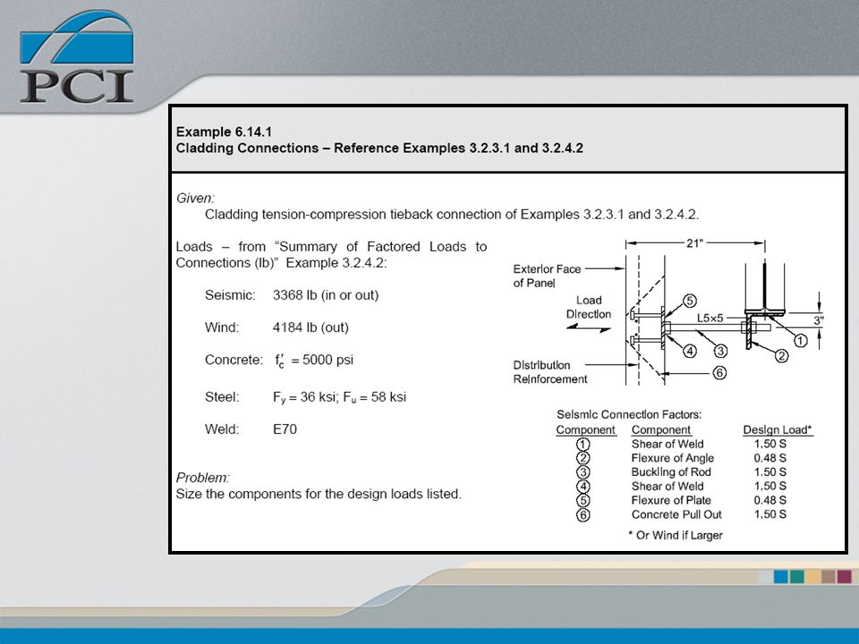
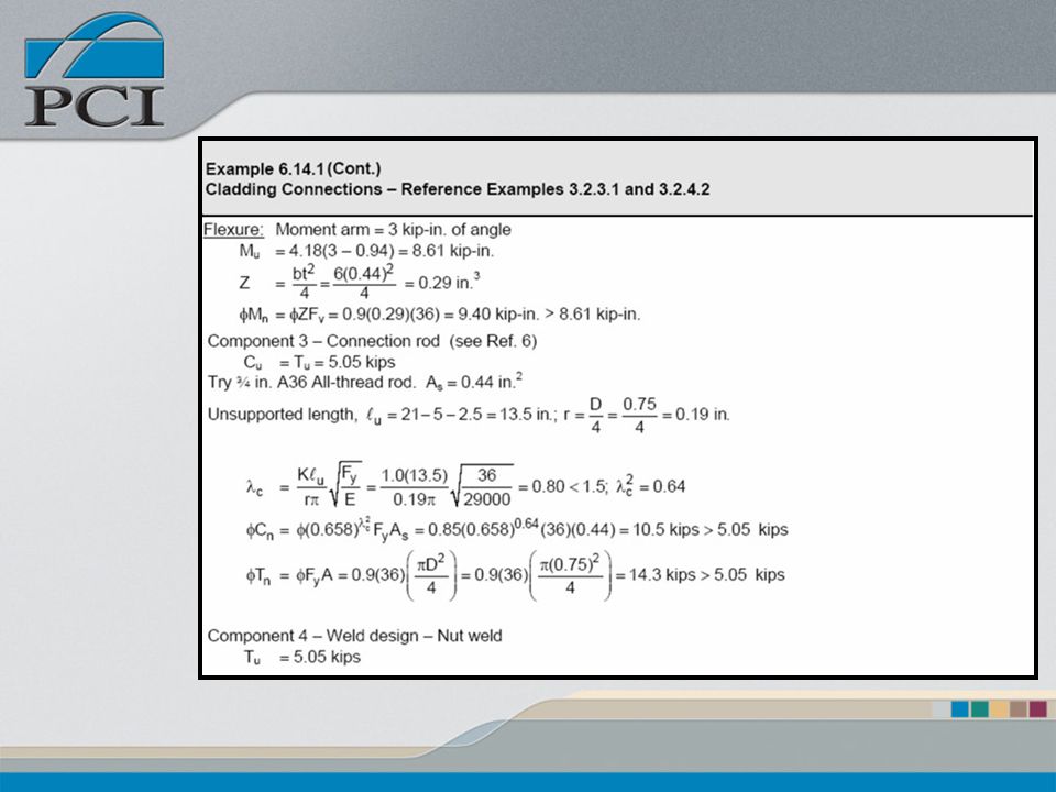
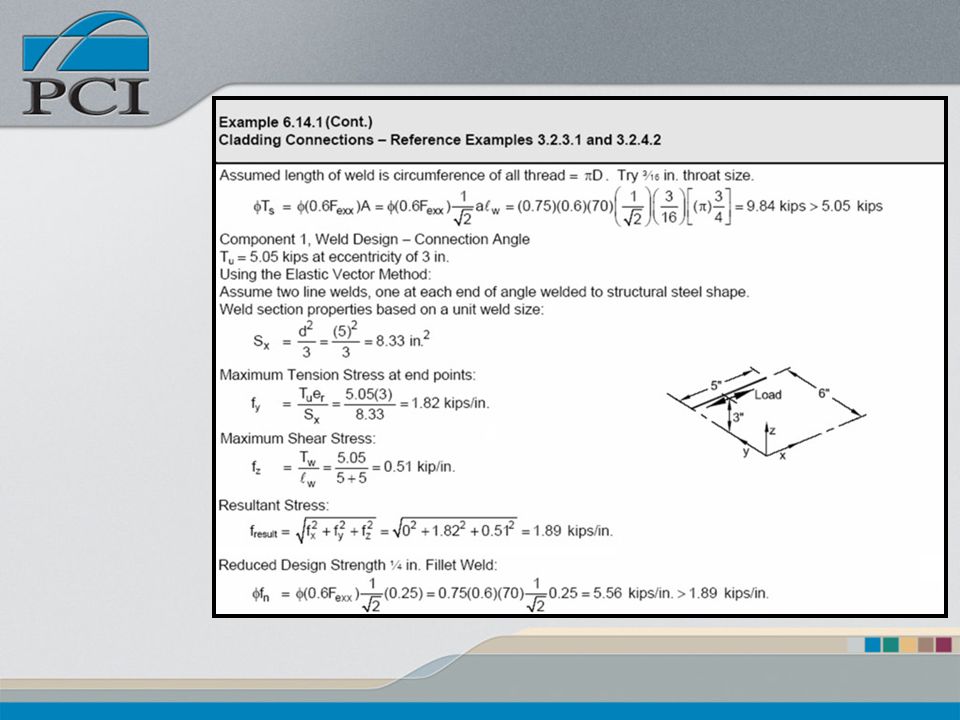
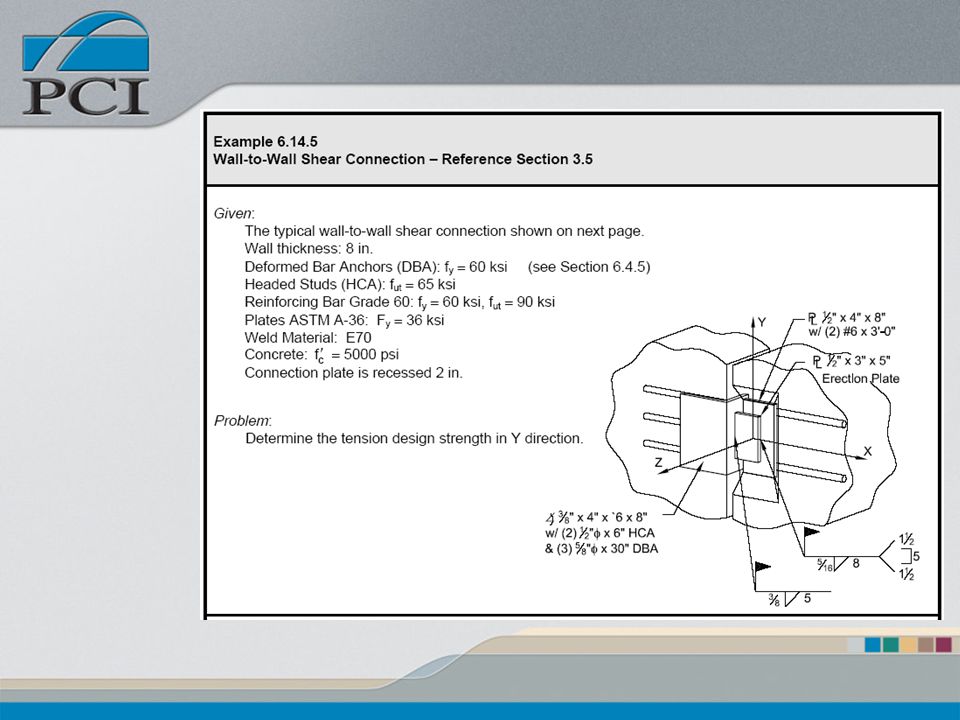
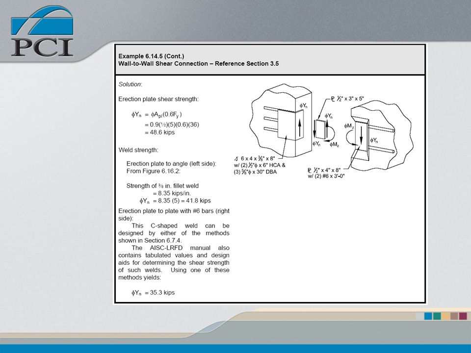
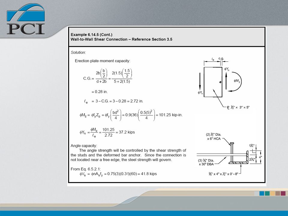
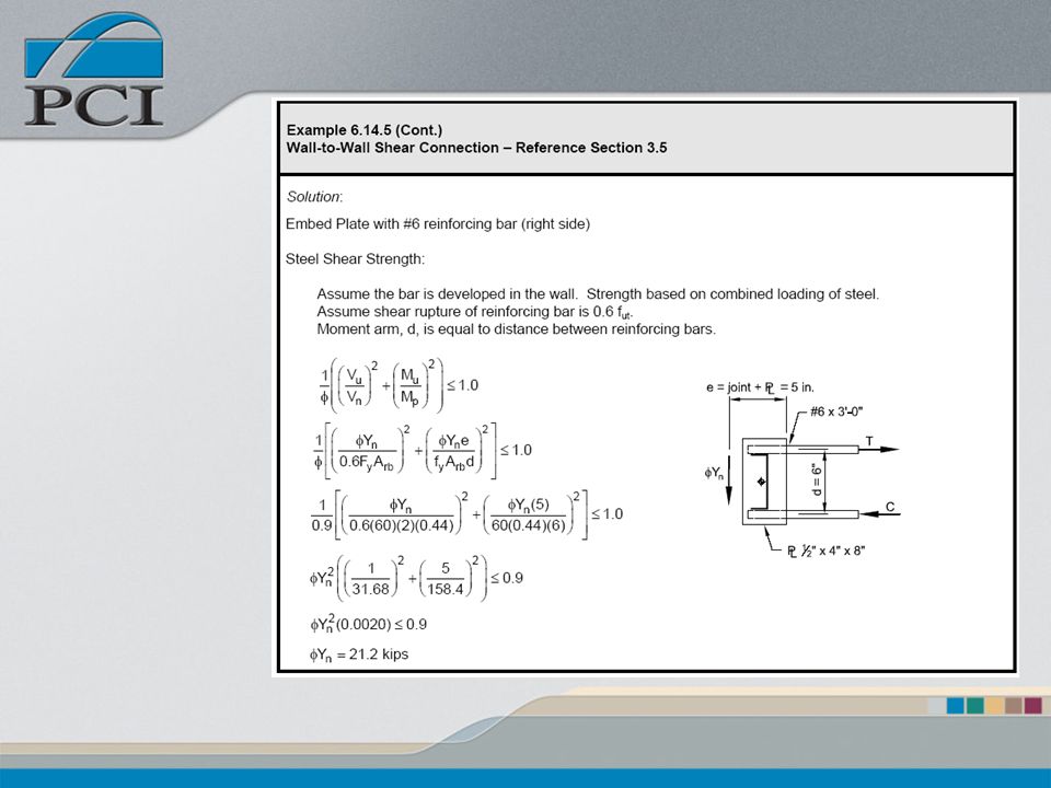
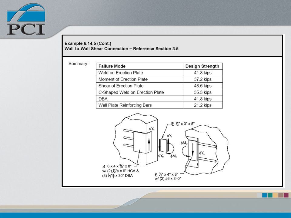
Completed Connection Examples
Examples Based Applied Loads Component Capacity Design of all components Embeds Erection Material Welds Design for specific load paths

86
Completed Connection Examples
Cladding “Push / Pull” Wall to Wall Shear Wall Tension Diaphragm to Wall Shear

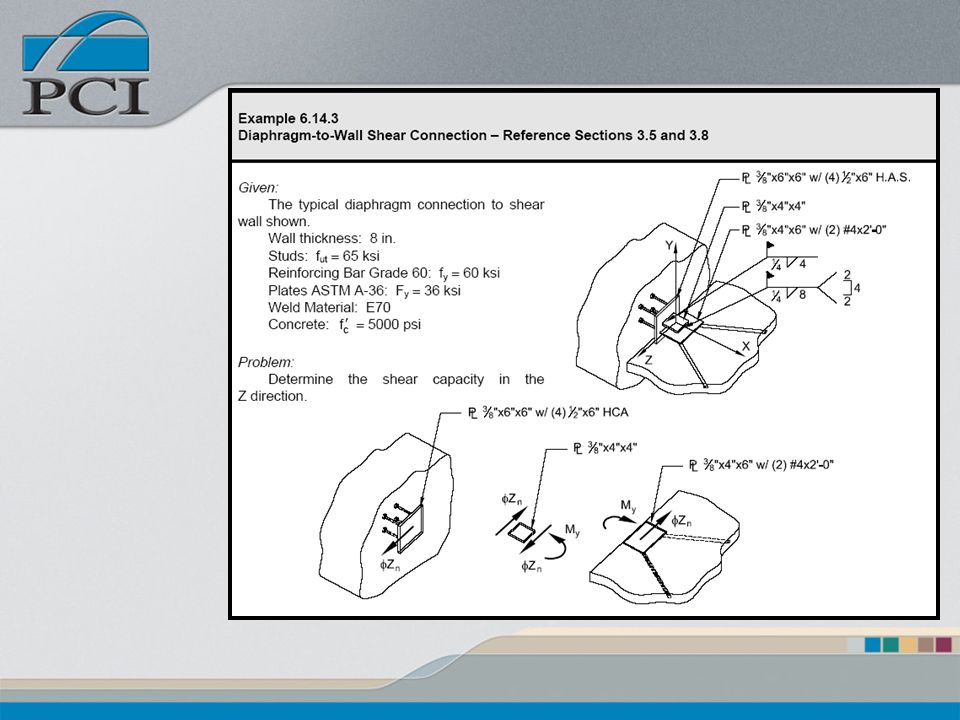
102
Questions?

Similar presentations


 BEAM- COLUMNS SHEAR / CONC. LOADS>")


