Download presentation
Presentation is loading. Please wait.

1
Chapter 23: Drilling and Related Hole-Making Processes
DeGarmo’s Materials and Processes in Manufacturing

2
23.1 Introduction Drilling is most common single machining operation
Drilling makes up 25% of machining Drilling occurs at the end of a tool within the material, four actions take place a the drill tip 1. A small hole is formed by the web—chips are not cut here in the normal sense. 2. Chips are formed by the rotating lips. 3. Chips are removed from the hole by the screw action of the helical flutes. 4. The drill is guided by lands or margins that rub against the walls of the hole

3
Nomenclature and Geometry of a Drill
FIGURE 23-1 Nomenclature and geometry of conventional twist drill. Shank style depends upon the method used to hold the drill. Tangs or notches prevent slippage: (a) straight shank with tang, (b) tapered shank with tang, (c) straight shank with whistle notch, (d) straight shank with flat notch.
 straight shank with tang, (b) tapered shank with tang, (c) straight shank with whistle notch, (d) straight shank with flat notch.")
4
23.2 Fundamentals of the Drilling Process
A conventional two-flute drill, with drill of diameter D, has two principal cutting edges rotating at an rpm rate of N and feeding axially. The rpm of the drill is established by the selected cutting velocity or cutting speed with V in surface feet per minute and D in inches.

5
Conventional Drill Geometry
FIGURE 23-2 Conventional drill geometry viewed from the point showing how the rake angle varies from the chisel edge to the outer corner along the lip. The thrust force increases as the web is approached.

6
23.3 Types of Drills The most common drills are twist drills
Twist drills have three parts The body: consisting of spiral grooves called flutes, separated by lands The point: a wide variety of geometry are used, but typically have a cone angel of 118°, and a rake angle of 24° The shank: a straight or tapered section where the drill is clamped.

7
Types of Twist Drills FIGURE 23-3 Types of twist
drills and shanks. Bottom to top: Straight-shank, three-flute core drill; straight-shank; taper-shank; bit-shank; straight-shank, high-helix angle; straight-shank, straight-flute; taper-shank, subland drill.

8
Drill Walking Standard drills have a straight line chisel point.
This point caused drills to “walk” along the surface This effect is counter by using centering techniques Center punches Pre-drilled guide holes for large holes Specialized methods of grinding the point address walking

9
Depth-to-Diameter Ratio
Standard drills typically are used to produce holes with a depth to diameter ratio of 3:1 Deeper holes result in drift of the tool decreasing hole straightness

10
Steps to High Accuracy Holes with Conventional Drills
FIGURE To obtain a hole that is accurate as to size and aligned on center (located), this 4 step sequence of operations is usual.
, this 4 step sequence of. operations is usual.")
11
23.4 Tool Holders for Drills
Straight-shank drills are typically held in chucks Three-jaw jacobs chucks: used on manual drill presses, require used of a key Collet chuck: used with carbide tools where high bearing thrust is used Quick change chucks: used were rapid change is needed Tapered shank drills held in mores taper of the machine spindle

12
Drill Chucks FIGURE Two of the most commonly used types of drill chucks are the 3-jaw Jacobs chuck (above) and the collet chuck with synthetic rubber support for jaws. (Courtesy of Jacobs Manufacturing Company.)
 and the collet chuck with synthetic rubber support for jaws. (Courtesy of Jacobs Manufacturing Company.)")
13
Correct Chucking of Carbide Drills
FIGURE Here are some suggestions for correct chucking of carbide drills.

14
23.5 Workholding for Drilling
For prototype pieces, stock material is held in simple clamping vises For high production rates, custom jigs are used Stock material is never to be held on the work table by hand

15
23.6 Machine Tools for Drilling
Drilling can be performed on: Lathes Vertical mills Horizontal mills Boring machines Machine centers Specialized machines designed specifically for drilling called “drill presses”

16
Requirements of a Drill Press
Drill presses must have sufficient power and thrust to perform cut Drill presses must be rigid enough to prevent chatter Drill press consist of a base, a work table, and a column that supports the powerhead and spindle

17
Specialized Drill Presses
Gang-drilling machines: independent columns, each with different drilling operation, work piece slid from one column to next Turret-type, upright drilling machines: used when numerous drilling operation are required in rapid succession, turret rotates needed tool into position for each operation Radial drilling machines: used on large workpieces, spindle mounts on radial arm, allowing drilling operations anywhere along the arm lenght

18
Specialized Drill Presses
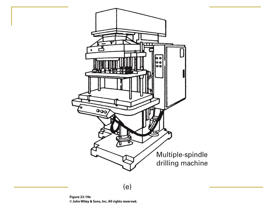
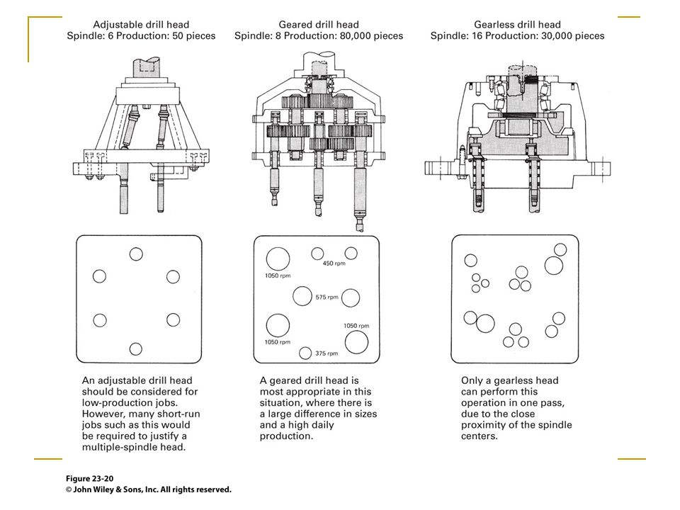
Multiple-spindle drilling machines: Single powerhead operates multiple spindles enabling multiple holes at one time, each hole can be unique

19
(a) Upright column drilling machine; (b) CNC turret drilling machine; (c) gang-drilling machine; (d) radial drill press; (e) multiple-spindle drilling machine
 Upright column drilling machine; (b) CNC turret drilling machine; (c) gang-drilling machine; (d) radial drill press; (e) multiple-spindle drilling machine")
20
(a) Upright column drilling machine
 Upright column drilling machine")
21
(b) CNC turret drilling machine
 CNC turret drilling machine")
23
(d) radial drill press
 radial drill press")
26
23.7 Cutting Fluids for Drilling

27
23.8 Counterboring, Countersinking, and Spot Facing
Counterboring: Follows a drilling operation, or in with drilling with a custom tool. Purpose is to produce a flat bottom so that bolt head or nut is below the surface with enough clearance for a tool. Countersinking: Similar to counterboring, but with a 60°, 82°, or 90° beveled bottom to accommodate flat-head screw or rivet. Spot facing: Machine minimum depth and diameter around hole to ensure full seating of a bolt head. Used on rough stock surfaces where corrosion or fatigue requirements require full seating

28
Counterboring and Countersinking Tools
FIGURE (a) Surfaces produced by counterboring, countersinking, and spot facing. (b) Counterboring tools: (bottom to top) interchangeable counterbore; solid, taper-shank counterbore with integral pilot; replaceable counterbore and pilot; replaceable counterbore, disassembled. (Courtesy of Ex-Cell- O Corporation and Chicago Latrobe Twist Drill Works.)
 Surfaces. produced by counterboring, countersinking, and spot facing. (b) Counterboring tools: (bottom. to top) interchangeable. counterbore; solid, taper-shank. counterbore with integral pilot; replaceable counterbore and. pilot; replaceable counterbore, disassembled. (Courtesy of Ex-Cell- O Corporation and Chicago. Latrobe Twist Drill Works.)")
29
23.9 Reaming Reams remove small amounts of material to ensure exact hole size and improve hole surface finish Reams are either hand operated or machined at slow speed Ream types Shell reams Expansion reams Adjustable reams Tapered reams

30
Ream Geometry FIGURE Standard nomenclature for hand and chucking reamers.

31
Types of Reams FIGURE 23-23 Types of
reamers: (top to bottom) Straightfluted rose reamer, straight-fluted chucking reamer, straight-fluted taper reamer, straight-fluted hand reamer, expansion reamer, shell reamer, adjustable insertblade reamer.
 Straightfluted. rose reamer, straight-fluted. chucking reamer, straight-fluted. taper reamer, straight-fluted. hand reamer, expansion reamer, shell reamer, adjustable insertblade. reamer.")
32
Summary Drilling is the most common machining operation
Drilling can be performed on a number of machine tools, drill presses are specialized machine tools for drilling only Drills come in a wide variety of types and tip geometries depending upon production rate and accuracy needed Hole geometries can be adjusted through the use of counterboring, countersinking and reaming

Similar presentations


 Straight chasers for cutting threads.>")
 Drilling Dr. Ahmed Abou El-Wafa.>")


 EIN 3390 Manufacturing Processes Spring, 2012 1.>")


