Download presentation
Presentation is loading. Please wait.

1
Teachers Name : Suman Sarker Telecommunication Technology Subject Name : Computer Controller System & Robotics Subject Code : 6872 Semester :7th Department : Electronics Ideal Institute Of Science & Technology (IIST)
")
2
Lecture – 09 Ch - 09 UNDERSTAND ROBOT GEAR AND LINKAGES

3
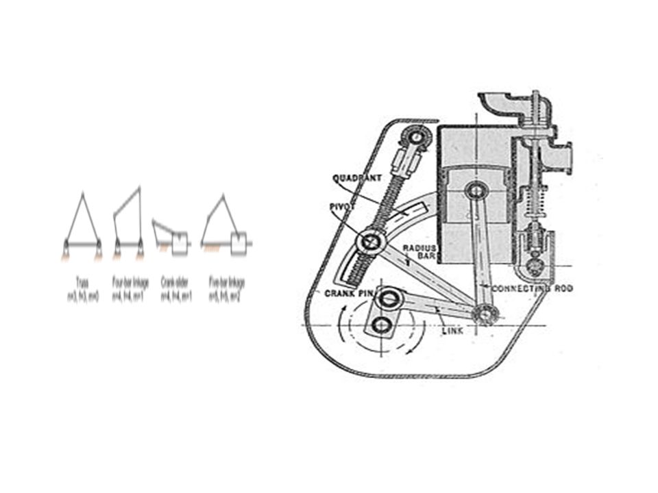
inkage (mechanical) From Wikipedia, the free encyclopedia This article is about assemblies of links designed to manage forces and movement. For other uses, see Linkage.Linkage Variable stroke engine (Autocar Handbook, Ninth edition)
.")
4
A mechanical linkage is an assembly of bodies connected to manage forces and movement. The movement of a body, or link, is studied using geometry so the link is considered to be rigid. [1] The connections between links are modeled as providing ideal movement, pure rotation or sliding for example, and are called joints. A linkage modeled as a network of rigid links and ideal joints is called a kinematic chain. [1]kinematic chain

6
Linkages may be constructed from open chains, closed chains, or a combination of open and closed chains. Each link in a chain is connected by a joint to one or more other links. Thus, a kinematic chain can be modeled as a graph in which the links are paths and the joints are vertices, which is called a linkage graph. The deployable mirror linkage is constructed from a series of rhombus or scissor linkages. An extended scissor liftscissor lift

8
The movement of an ideal joint is generally associated with a subgroup of the group of Euclidean displacements. The number of parameters in the subgroup is called the degrees of freedom (DOF) of the joint. Mechanical linkages are usually designed to transform a given input force and movement into a desired output force and movement. The ratio of the output force to the input force is known as themechanical advantage of the linkage, while the ratio of the input speed to the output speed is known as the speed ratio. The speed ratio and mechanical advantage are defined so they yield the same number in an ideal linkagedegrees of freedommechanical advantagespeed ratio
 of the joint. Mechanical linkages are usually designed to transform a given input force and movement into a desired output force and movement. The ratio of the output force to the input force is known as themechanical advantage of the linkage, while the ratio of the input speed to the output speed is known as the speed ratio. The speed ratio and mechanical advantage are defined so they yield the same number in an ideal linkagedegrees of freedommechanical advantagespeed ratio.")
9
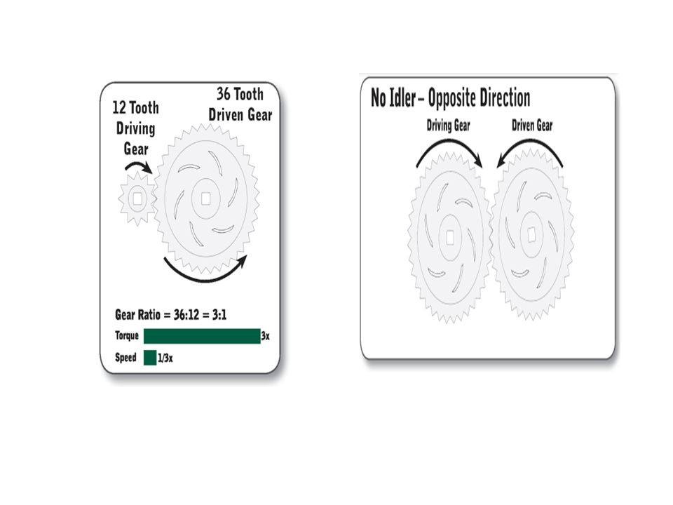
Introduction to Gears As learned in Unit 5: Speed, Power, Torque, and DC Motors, a motor can generate a set amount of power; that is, it can provide a specific amount of energy every second. Since there is only so much energy to go around, and energy is the product of torque and speed, there is an inherent trade-off between torque and speed.

13
Gears control power transmission in three ways: 1. Changing the direction through which power is transmitted. 2. Changing the amount of force or torque. 3. Changing the speed of rotation, typically measured in revolutions per minute (RPM). Spur Gears Spur gears have been used since ancient times. They are used primarily to transfer speed and torque between parallel shafts. The most recognizable gear form, spur gears have many advantages of other types due to their simple design, low manufacturing costs, and easy maintenance. One downside to spur gears is that they are noisy due to the impacts of meshing teeth.
. Spur Gears Spur gears have been used since ancient times. They are used primarily to transfer speed and torque between parallel shafts. The most recognizable gear form, spur gears have many advantages of other types due to their simple design, low manufacturing costs, and easy maintenance. One downside to spur gears is that they are noisy due to the impacts of meshing teeth..")
14
Next Lecture ROBOT GEAR AND LINKAGES

Similar presentations