Download presentation
Presentation is loading. Please wait.

1
Umm Al-Qura University Department of Civil & Structural Engineering
Design of reinforced concrete II Ribbed and Hollow Block Floors Lecture (4)
")
2
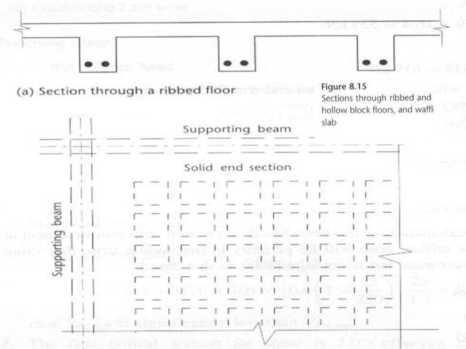
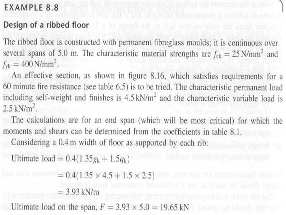
Ribbed and Hollow Block Floors
The ribbed floor is formed using temporary or permanent shuttering while the hollow block floor is generally constructed with block made of clay or concrete containing lightweight aggregate. Many design calculations ignore these block contribution to the slab strength. Major benefit is the reduction in weight. They are economical for building with spans 5m and moderate live load and not suitable for heavy loads such as garages and warehouses.

3
Near to the support the blocks are stopped off and
the slab is made solid (greater shear strength). The ribs should be checked for shear at their junction with the solid slab. The slabs are usually made solid under partitions and concentrated loads. During construction the blocks should be well soaked in water prior to placing concrete, otherwise shrinkage cracking of the top concrete flange is liable to occur.
. The ribs should be checked for shear at their junction. with the solid slab. The slabs are usually made solid under partitions and. concentrated loads. During construction the blocks should be well soaked. in water prior to placing concrete, otherwise shrinkage. cracking of the top concrete flange is liable to occur.")
6
The thickness of concrete flange should not be less than:
40 mm or one-tenth of the clear distance between ribs with permanent blocks. 50 mm or one-tenth of the clear distance between ribs without permanent blocks. The rib width will be governed by (Section 6.1): Cover Bar-spacing Fire resistance
: Cover. Bar-spacing. Fire resistance.")
7
The ribs should be spaced no further apart than 1.5m.
Calculation of reinforcement will require evaluation of effective flange breadths for T-beams (see Chapter 7). For shear design bw taken as the breadth of the rib. Span-effective depth ratio is based on the shorter span. Basic values given in figure 6.3 multiplied by 0.8.
. For shear design bw taken as the breadth of the rib. Span-effective depth ratio is based on the shorter span. Basic values given in figure 6.3 multiplied by 0.8.")
8
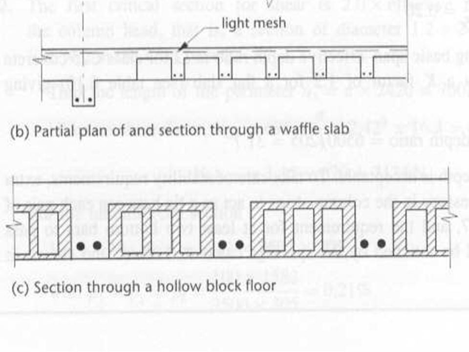
Light reinforcing mesh in the topping flange can give
extra strength and durability. This can resist cracking due to shrinkage or thermal movement. Area of mesh equivalent to 0.13% of the topping flange will be adequate.

Similar presentations