Download presentation
Presentation is loading. Please wait.

1
Department of Civil and Environmental Engineering, The University of Melbourne Finite Element Modelling Applications (Notes prepared by A. Hira – modified by N. Haritos)
.")
2
Introduction FEA is a powerful tool. Analyses structural behaviour of complex problems. Must be used with full confidence. Understanding of the structural problem. Knowledge on the limitations and features of the FEA. This lecture will illustrate some examples of FEA applications identifying the key problem to be investigated and some of the difficulties.

3
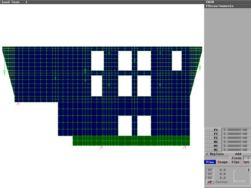
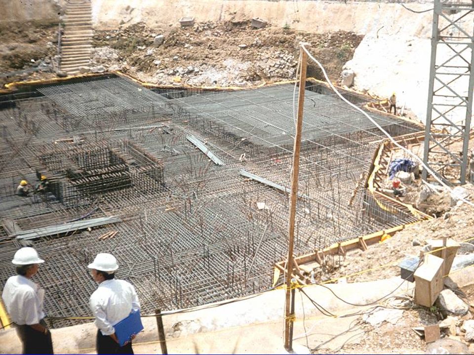
Transfer Structure New 27 storey hotel structure built over an existing 10 storey department store Challenge in the project was to design the transfer structures at the base Typically store has a large column spacing for flexibility in retail space and Hotel has small column spacing

4
FEA Required for the Following Reasons The structure is highly irregular. The load paths were sensitive to the door openings. Identify regions where tension prevailed. (Important for RC structure) Required to have clear understanding on the secondary stresses due to prestressing. Parametric studies needed to be carried out quickly, efficiently and accurately in a fast track program.
 Required to have clear understanding on the secondary stresses due to prestressing. Parametric studies needed to be carried out quickly, efficiently and accurately in a fast track program..")
5
Stages for FEA Application Conceptual Stage Required for sizing purposes. Manual structural assessment using a simple strut-tie model. Identify level of stresses and critical regions. Formulate finite element model (FEM)
.")
6
Stages for FEA Application Preliminary Stage FEA was extensively applied to fine tune suitable locations for door openings. Geometry of the wall was finalised and prestressing procedure was determined.

7
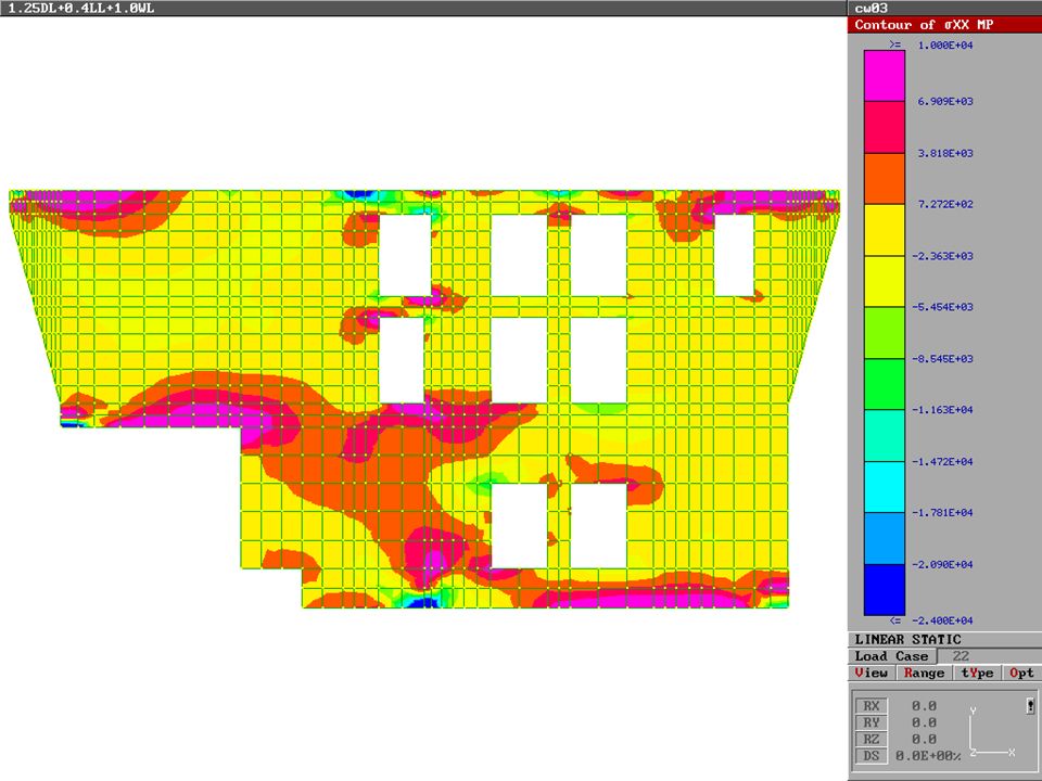
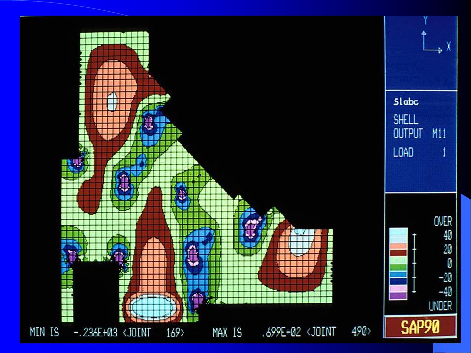
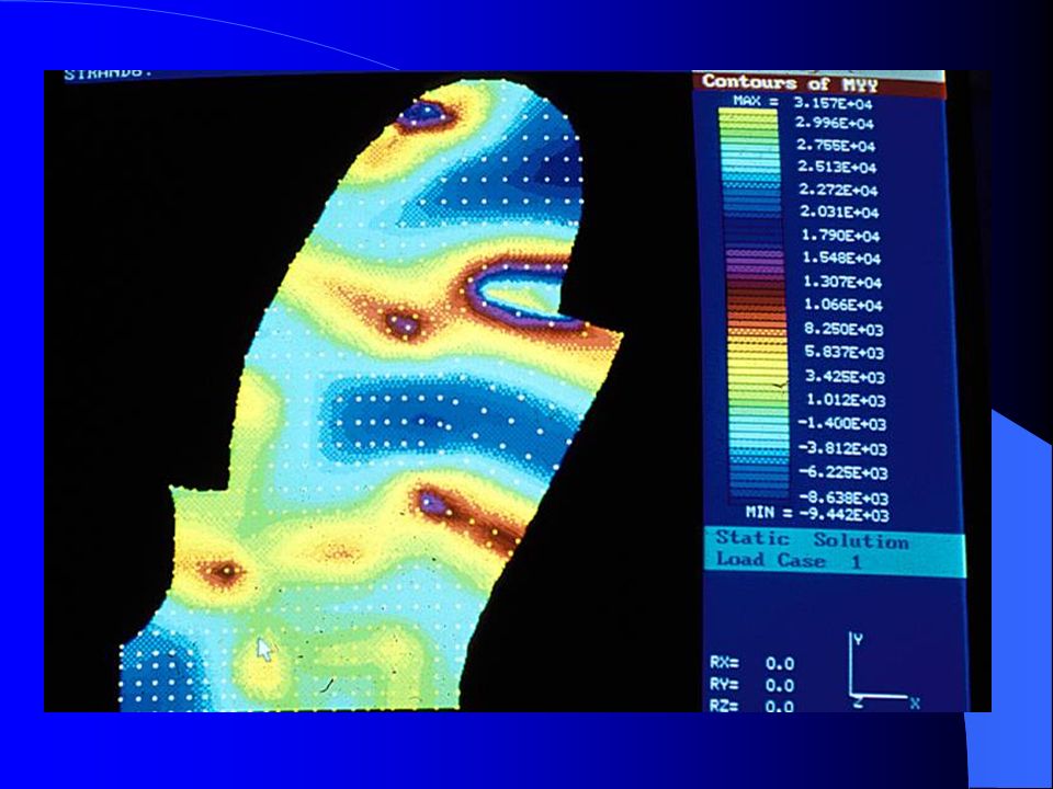
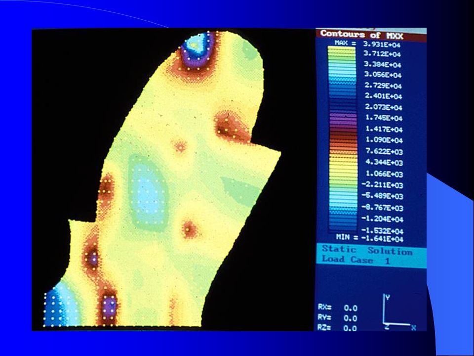
Detailed Analysis Stage Detailed analysis carried out for all load combinations. Typical stress distributions determined. Correct interpretation of FEA results for RC elements is important. FEA determines regions of high tensile stresses under serviceability

8
Detailed Analysis Stage Enables designer to evaluate prestressing required for crack free environment. Considerable time was allocated to checking the results. The most effective and efficient method of checking FEA results is by inspecting graphical outputs. Simple equilibrium checks and checking of the load cases is essential.

9
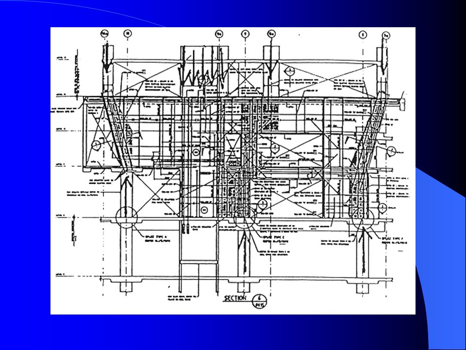
Detailed Design Stage Interpreting the results of FEA is a critical phase. Converting to Reinforcement drawings is a most important phase. This stage deserves greater attention as it is often overshadowed by the glamour associated with the analytical modelling and analysis phase.

10
Detailed Design Stage For reinforced concrete the designer must have a thorough understanding of the two dimensional stress state. Skilful use of the powerful graphical post-processing capabilities,

17
Structural Optimisation Spectacular progress over the last two decades. Obvious imbalance between the extraordinary growth of structural optimisation theory and its minimal application to structural design of engineering structures. Readily applied in the areas of space and aeronautical industries and in the automobile industry.

18
Structural Optimisation Currently optimisation process is carried out by trial and error involving engineering judgement by the designer. Systematic procedures to arrive at optimal solutions is desirable. Closer collaboration between research and industry is required.

19
Optimisation of Wall Cantilever Wall system for tall building. Governing Criteria is Stiffness (governed by lateral deflection at top of building) The objective of the optimisation process is to obtain the optimum solution. minimum volume of material. maintaining a target stiffness in terms of the lateral displacement at the top of the structure.
 The objective of the optimisation process is to obtain the optimum solution. minimum volume of material. maintaining a target stiffness in terms of the lateral displacement at the top of the structure..")
20
Optimisation of Wall Optimal solution = wall thickness profile up the height of the building will continually change. Solution not practical. Minimise the # of transitions in wall thick for practical and economic reasons. The procedure involves a systematic sizing-analysing and resizing process.

21
Coupled Cantilever Wall

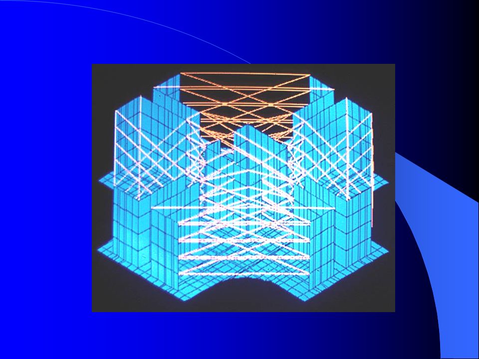
22
Typical Highrise Building

23
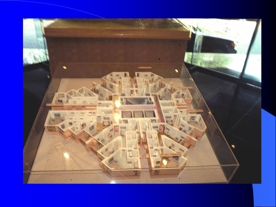
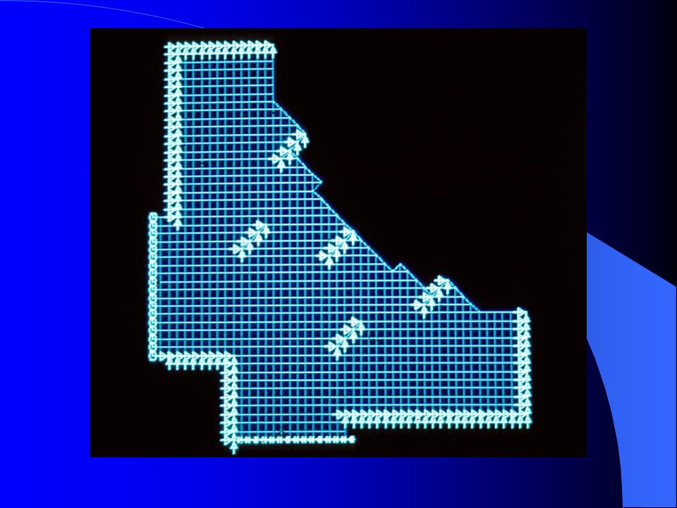
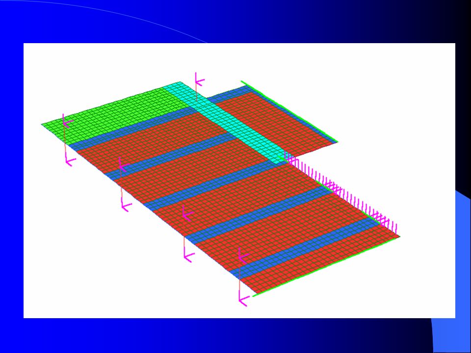
Complex Slab Shape The reasons for using FEA design of flat slab for a High- Rise Slab: The project consists of 17 buildings ranging from 30 to 38 storeys with similar slab layout. (optimisation results in economy). The slab is highly irregular. The support system is not in a recti-linear grid. Further studies in the inelastic areas were required to investigate the slab behaviour under severe earthquake conditions.
. The slab is highly irregular. The support system is not in a recti-linear grid. Further studies in the inelastic areas were required to investigate the slab behaviour under severe earthquake conditions..")
29
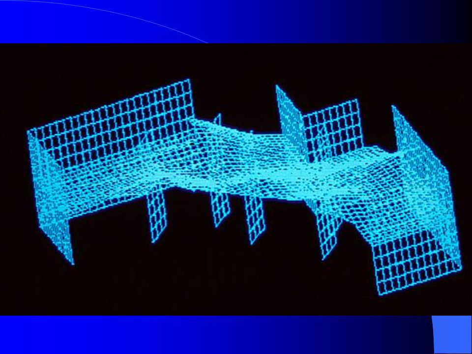
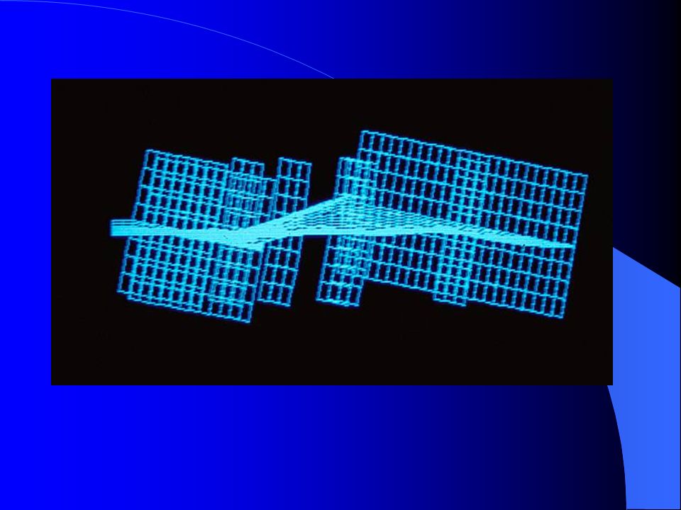
Complex Slabs FEA analysis appropriate for: Bending moments and shear forces. Deflection characteristics. Dynamic characteristics including natural frequencies and deflections due to heel-drop loadings.

Similar presentations


 Superstructure – Concrete Bridges>")


