Download presentation
Presentation is loading. Please wait.

2
ONE-WAY SLAB

3
Introduction A slab is structural element whose thickness is small compared to its own length and width. Slabs are usually used in floor and roof construction. One-way slabs: When the ratio of the longer to the shorter side (L/ S) of the slab is at least equal to 2.0, it is called one-way slab. Under the action of loads, it is deflected in the short direction only, in a cylindrical form. Therefore, main reinforcement is placed in the shorter direction, while the longer direction is provided with shrinkage reinforcement to limit cracking. When the slab is supported on two sides only, the load will be transferred to these sides regardless of its longer span to shorter span ratio, and it will be classified as one-way slab.
 of the slab is at least equal to 2.0, it is called one-way slab. Under the action of loads, it is deflected in the short direction only, in a cylindrical form. Therefore, main reinforcement is placed in the shorter direction, while the longer direction is provided with shrinkage reinforcement to limit cracking. When the slab is supported on two sides only, the load will be transferred to these sides regardless of its longer span to shorter span ratio, and it will be classified as one-way slab.")
5
Accordingly, main reinforcement is required in the two directions.
One way slab; (a) classification; (b) reinforcement Two-way Slabs: When the ratio (L/ S) is less than 2.0, it is called two-way slab. Bending will take place in the two directions in a dish-like form. Accordingly, main reinforcement is required in the two directions.
 classification; (b) reinforcement. Two-way Slabs: When the ratio (L/ S) is less than 2.0, it is called two-way slab. Bending will take place in the two directions in a dish-like form. Accordingly, main reinforcement is required in the two directions.")
6
Two way slabs

7
One-way Slabs In this section, two types will be discussed, one-way solid slabs and one-way ribbed slabs. One-way Solid Slabs Minimum Thickness To control deflection, ACI Code specifies minimum thickness values for one-way solid slabs, shown in Table. Minimum thickness of one-way solid slabs where l is the span length in the direction of bending.

8
Minimum Concrete Cover

9
Design Concept One-way solid slabs are designed as a number of independent 1 m wide strips which span in the short direction and supported on crossing beams. Maximum Reinforcement Ratio One-way solid slabs are designed as rectangular sections subjected to shear and moment. Thus, the maximum reinforcement ratio ρmax is not to exceed Shrinkage Reinforcement Ratio According to ACI Code and for steels yielding at , the shrinkage reinforcement is taken not less than of the gross concrete area, or where, b = width of strip, and h = slab thickness.

10
Minimum Reinforcement Ratio
According to ACI Code , the minimum flexural reinforcement is not to be less than the shrinkage reinforcement, or Spacing Of Flexural Reinforcement Bars Flexural reinforcement is to be spaced not farther than three times the slab thickness, nor farther apart than 45 cm, center-to-center. Spacing Of Shrinkage Reinforcement Bars Shrinkage reinforcement is to be spaced not farther than five times the slab thickness, nor farther apart than 45 cm, center-to-center.

11
Loads Assigned to Slabs
(1) Own weight of slab: (2) Weight of slab covering materials: - Sand fill with a thickness of about 5 cm, Cement mortar, 2.5 cm thick. - Tiling A layer of plaster about 2 cm in thickness. (3) Live Load: Table shows typical values used by the Uniform Building Code (UBC).
 Own weight of slab: (2) Weight of slab covering materials: - Sand fill with a thickness of about 5 cm, Cement mortar, 2.5 cm thick. - Tiling. A layer of plaster about 2 cm in thickness. (3) Live Load: Table shows typical values used by the Uniform Building Code (UBC).")
12
Minimum live Load values on slabs

13
Loads Assigned to Beams
(4) Equivalent Partition Weight: This load is usually taken as the weight of all walls carried by the slab divided by the floor area and treated as a dead load rather than a live load. Loads Assigned to Beams The beams are usually designed to carry the following loads: - Their own weights. - Weights of partitions applied directly on them. - Floor loads. The floor loads on beams supporting the slab in the shorter direction may be assumed uniformly distributed throughout their spans.
 Equivalent Partition Weight: This load is usually taken as the weight of all walls carried by the slab divided by the floor area and treated as a dead load rather than a live load. Loads Assigned to Beams. The beams are usually designed to carry the following loads: - Their own weights. - Weights of partitions applied directly on them. - Floor loads. The floor loads on beams supporting the slab in the shorter direction may be assumed uniformly distributed throughout their spans.")
14
Approximate Structural Analysis
ACI Code permits the use of the following approximate moments and shears for design of continuous beams and one-way slabs, provided: 1. Positive Moment: a. End Spans: When discontinuous end unrestrained, When discontinuous end is integral with support, where ln is the corresponding clear span length b. Interior Spans: 2. Negative Moment: a. Negative moment at exterior face of first interior support: Two spans,

15
More than two spans, where ln is the average of adjacent clear span lengths. b. Negative moment at other faces of interior supports: c. Negative moment at interior face of exterior support: Support is edge beam, Support is a column, 3. Shear: a. Shear in end members at face of first interior support: b. Shear at face of all other supports: where ln is the corresponding clear span length.

16
(a) Two spans, exterior edge unrestrained; (b) two spans,
support is spandrel beam; (c) more than two spans, exterior edge unrestrained; (d) more than two spans, support is spandrel beam; (e) two spans, shearing force diagram
 more than two spans, exterior edge unrestrained; (d) more than two spans, support is spandrel beam; (e) two spans, shearing force diagram.")
17
Summary of One-way Solid Slab Design Procedure
Once design compressive strength of concrete and yield stress of reinforcement are specified, the next steps are followed: 1. Select representative 1 m wide design strip/strips to span in the short direction. 2. Choose a slab thickness to satisfy deflection control requirements. When several numbers of slab panels exist, select the largest calculated thickness. 3. Calculate the factored load Wu by magnifying service dead and live loads according to this equation

18
(a) Representative strip and reinforcement; (b) strip and loads
 Representative strip and reinforcement; (b) strip and loads")
19
4. Draw the shear force and bending moment diagrams for each of the strips.
5. Check adequacy of slab thickness in terms of resisting shear by satisfying the following equation:

20
6. Design flexural and shrinkage reinforcement:
Flexural reinforcement ratio is calculated from the following equation: Make sure that the reinforcement ratio is not larger than ¾ ρb Compute the area of shrinkage reinforcement, where Select appropriate bar numbers and diameters for both, main and secondary reinforcement. Check reinforcement spacing, modify your bar selection if needed. 7. Draw a plan of the slab and representative cross sections showing the dimensions and the selected reinforcement.

21
Section A-A

22
Example (8.1): Using the ACI Code approximate structural analysis, design for a warehouse, a continuous one-way solid slab supported on beams 4.0 m apart as shown. Assume that the beam webs are 30 cm wide. The dead load is 300 kg/m2 in addition to own weight of the slab, and the live load is 300 kg/m2 Solution : 1- Select a representative 1 m wide slab strip:

23
Representative strip

24
For one-end continuous spans, Slab thickness is taken as 18 cm.
2- Select slab thickness: The clear span length For one-end continuous spans, Slab thickness is taken as 18 cm. 3- Calculate the factored load Wu per unit length of the selected strip:

25
4- Evaluate the maximum factored shear forces and
bending moments in the strip: The results are shown in the following table. Points at which moments and shear are calculated.

26
Points at which moments and shear are evaluated
5- Check slab thickness for beam shear:

27
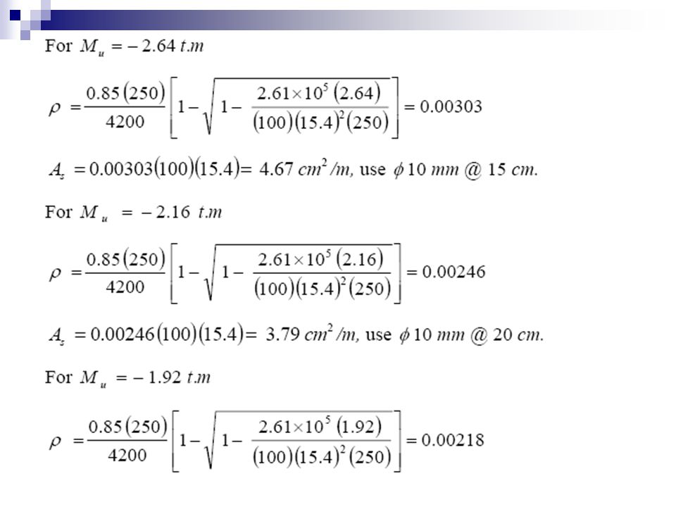
6- Design flexural and shrinkage reinforcement:
Steel reinforcement ratios are then calculated, and be checked against minimum and maximum code specified limits, where

28
7- Prepare neat sketches showing the reinforcement and slab thickness:

29
(continued); (c) Section A-A; (d) reinforcement details
; (c) Section A-A; (d) reinforcement details")
30
Example (8.2): Design the slab shown in Example (8.1) using any available structural analysis software. Solution : 1- Select a representative 1 m wide slab strip: The selected representative strip is shown. 2- Select slab thickness: Same as in Example (8.1), the thickness is taken as 18 cm. 3- Calculate the factored load Wu per unit length of the selected strip: For a strip 1 m wide, 4- Evaluate the maximum factored shear forces and bending moments in the strip:
, the thickness is taken as 18 cm. 3- Calculate the factored load Wu per unit length of the selected strip: For a strip 1 m wide, 4- Evaluate the maximum factored shear forces and bending moments in the strip:")
31
Shearing force and bending moment diagrams

32
5- Check slab thickness for beam shear:
6- Design flexural and shrinkage reinforcement: Steel reinforcement ratios are calculated and checked against minimum and maximum code specified limits.

35
7- Prepare neat sketches showing the reinforcement and slab thickness:

36
Section A-A

Similar presentations


: Redesign the stair shown in Example (10.1) if it is a cantilever type of a clear span of 1.6 m. Solution : Minimum stair thickness required.>")


: A rectangular beam has the dimensions shown in Figure 4.12.a and is loaded with a 40 ton concentrated.>")