Download presentation
Presentation is loading. Please wait.

2
SHEAR IN BEAMS

3
Introduction Loads applied to beams produce bending moments, shearing forces, as shown, and in some cases torques. Beams are usually designed for bending moment first; thus cross sectional dimensions are evaluated along with the required amounts of longitudinal reinforcement. Once this is done, sections should be checked for shear to determine whether shear reinforcement is required or not.

4
Shear in Homogeneous, Elastic Beams
Loaded beam and orientation of cracks

5
The normal stresses resulting from bending are given by the following equation as proved by the classical bending theory The shearing stresses are given by the following equation proved in the most classical mechanics of materials books

6
Where is the shearing force at the considered section, is the moment of the area of the section located between the point where the shearing stresses are calculated and the extreme fiber of the section about the neutral axis, is the moment of inertia about the neutral axis, and b is the width of the section at the point where shearing stresses are calculated. In an attempt to establish the cracking pattern, four elements situated at different distances from the neutral axis are studied.

7
Types of Shear Cracks Two types of inclined cracking occur in beams: flexure-shear cracking and web-shear cracking. A. Flexure-Shear Cracks The most common type, develops from the tip of a flexural crack at the tension side of the beam and propagates towards mid depth until it is checked on the compression side of the beam. For these cracks to form, the bending moment must exceed the cracking moment of the cross section and a significant shear must exist.

8
Types of cracks and associated internal forces: (a) orientation of cracks; (b) shear force diagram; (c) bending moment diagram
 orientation of cracks; (b) shear force diagram; (c) bending moment diagram")
9
Nominal Shear Stress B. Web Shear Cracks
Web shear cracking begins from an interior point in a member at the level of the centroid of uncracked section and moves on a diagonal path to the tension face when the diagonal tensile stresses produced by shear exceed the tensile strength of concrete. This type of cracking is common on beams with thin webs and in regions of high shear and small moment. This combination exists adjacent to simple supports or at points of inflection in continuous beams. Nominal Shear Stress The only equation available to relate shear stress to shearing force is derived for a beam of constant cross section constructed of a homogeneous elastic material. Unfortunately, Eq. (4.2) can not be applied to reinforced concrete beams for the following reasons:
 can not be applied to reinforced concrete beams for the following reasons:")
10
Reinforced concrete is nonhomogeneous material.
Concrete is not elastic. Variable extent of cracking along the length of a beam, making it impossible to determine cross-sectional properties. Therefore, the ACI Code has adopted a simple procedure for establishing the magnitude of shear stress v on a cross section where = nominal shear stress = shearing force at specified section = width of web of cross section = effective depth of the section.

11
According to ACI Code , design of cross sections subject to shear should be based on the following equation.

12
Strength of Concrete in Shear
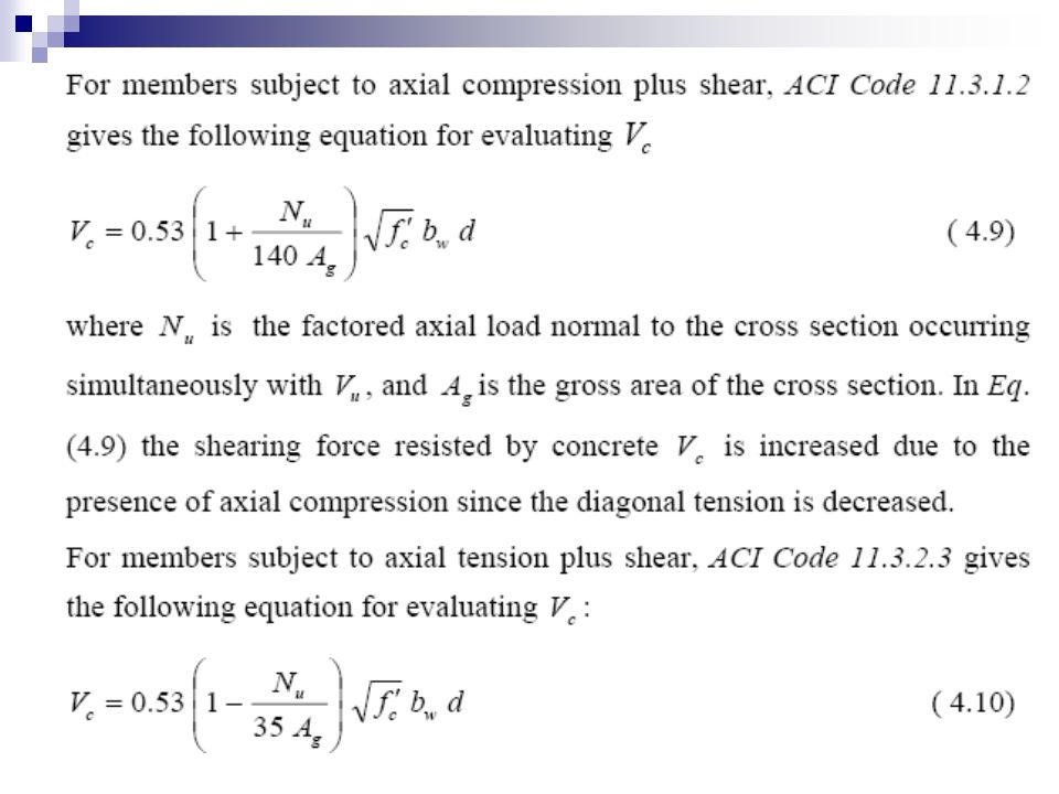
Shear strength of concrete Vc is evaluated by loading a plain concrete beam to failure. Shear stresses are computed by dividing the shearing force resisted by concrete Vc by bwd. Strength of concrete in shear is directly proportional to the strength of concrete in tension, inversely proportional to the magnitude of bending moment at the section under consideration, and directly proportional to the reinforcement ratio of flexural reinforcement. For the sake of simplicity Vc is assumed to be the same for beams with or without shear reinforcement. For members subject to shear and bending only, ACI Code gives the following equation for evaluating Vc

13
where Vu is the factored shearing force, Mu is the factored bending moment occurring simultaneously with Vu at section considered, ρw is the reinforcement ratio of the web, and d is the effective depth of the beam should not exceed 1.0, and Vc should not exceed

16
Strength Provided by Shear Reinforcement
When the nominal shearing force Vn exceeds the shearing force that can be resisted by concrete alone Vc , shear reinforcement, in any of the forms shown in the following section, can be used. Types of Shear Reinforcement When shear reinforcement is required, the following types of shear reinforcement are permitted by ACI Code , as shown. a. Vertical Stirrups; b. Inclined stirrups making an angle of 45 degree or more with longitudinal tension reinforcement; c. Longitudinal reinforcement with bent portion making an angle of 30 degree or more with the tension reinforcement; d. Spirals, circular ties, or hoops; e. Combination of stirrups and bent longitudinal reinforcement. Before diagonal cracking occurs, the stirrups remain unstressed. After cracking, the stress in the stirrups increases as they pick up a portion of the load formerly carried by the uncracked concrete.

18
Types of shear reinforcement: (a) vertical stirrups; (b) inclined
stirrups; (c) bent-up bars (two groups); (d) bent-up bars (three groups)
 bent-up bars (two groups); (d) bent-up bars (three groups)")
19
Minimum Amount of Shear Reinforcement
The instant diagonal crack forms, the tension carried by the concrete must be transferred to the stirrups if the beam is not to split into two sections. To ensure that the stirrups will have sufficient strength to absorb the diagonal tension in the concrete, ACI Code states that a minimum area of shear reinforcement is to be provided in concrete members where the factored shearing force u V exceeds half the shear strength provided by concrete 0.50 Φ Vc , except for the following: Slabs; ribbed or solid. Footings. Beams with total height not greater than 25 cm, 2.5 times thickness of flange, or 0.50 the width of web, whichever is the greatest. The exceptions were made because there is a possibility of load sharing between weak and strong areas. This minimum area is given by ACI Code

20
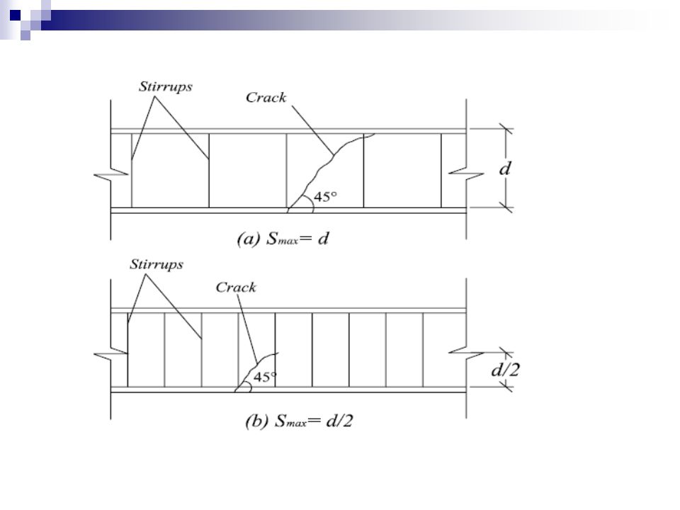
Maximum Stirrup Spacing
where Av is the area of shear reinforcement within a distance S , bw is the web width, S is the spacing of shear reinforcement, and fys is the yield stress of the shear reinforcement. Maximum Stirrup Spacing The assumption made in Eq. (4.15) is that one or more stirrups cross each potential diagonal crack in order to prevent the beam from splitting into two sections between stirrups. To ensure that, this requirement is satisfied, ACI Code through specifies the following limits for maximum spacing of shear reinforcement. A. Vertical Stirrups
 is that one or more stirrups cross each potential diagonal crack in order to prevent the beam from splitting into two sections between stirrups. To ensure that, this requirement is satisfied, ACI Code through specifies the following limits for maximum spacing of shear reinforcement. A. Vertical Stirrups.")
21
B. Inclines stirrups and Bent-up Bars:

23
Maximum stirrup spacing

24
Some stirrup shapes: (a) open; (b) closed;
(c) closed; (d) two sets; (e) two sets
 closed; (d) two sets; (e) two sets.")
25
Location of critical section for shear

26
Punching shear: (a) punching shear failure of an isolated
footing; (b) actual failure surface; (c) assumed failure surface
 actual failure surface; (c) assumed failure surface.")
27
Punching shear surface for isolated footings:
(a) rectangular column; (b) circular column
 rectangular column; (b) circular column.")
28
Design Procedure for Beams
Summary of ACI Shear Design Procedure for Beams Once the beam is designed for moment, thus establishing the concrete dimensions and the required longitudinal reinforcement, the beam is designed for shear as explained in the next steps. 1. Draw the shearing force diagram and establish the critical section for shear.

29
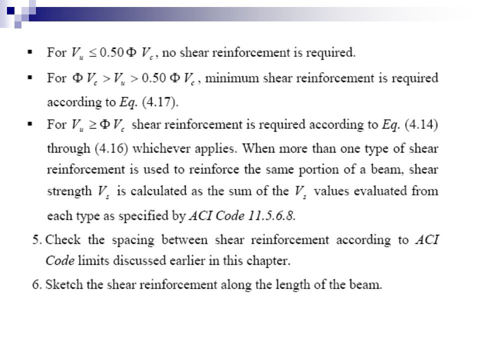
2. Calculate the nominal capacity of concrete in shear using any of Equations (4.7) through (4.10) as applies. 3. Check whether the chosen concrete dimensions are adequate for ensuring a ductile mode of failure by satisfying the following equation: where u V is the factored critical shearing force acting on the beam. If Eq. (4.22) is not satisfied, the concrete dimensions should be increased. 4. Classify the factored shearing forces acting on the beam according to the following:
 is not satisfied, the concrete dimensions should be increased. 4. Classify the factored shearing forces acting on the beam according to the following:")
Similar presentations


: A rectangular beam has the dimensions shown in Figure 4.12.a and is loaded with a 40 ton concentrated.>")


