Download presentation
Presentation is loading. Please wait.

1
EI 202 Manufacturing Processes
Dr. Apiwat Muttamara

2
Classifications of Metal Alloys
Steels Ferrous Nonferrous Cast Irons Cu Al Mg Ti <1.4wt%C 3-4.5 wt%C Ferrous alloys: iron is the prime constituent -Alloys that are so brittle that forming by deformation is not possible ordinary are cast

3
Materials Ferrous metals: carbon-, alloy-, stainless-, tool-and-die steels Non-ferrous metals: aluminum, magnesium, copper, nickel, titanium, superalloys, refractory metals, beryllium, zirconium, low-melting alloys, gold, silver, platinum, … Plastics: thermoplastics (acrylic, nylon, polyethylene, ABS,…) thermosets (epoxies, Polymides, Phenolics, …) elastomers (rubbers, silicones, polyurethanes, …) Ceramics, Glasses, Graphite, Diamond, Cubic Boron Nitride Composites: reinforced plastics, metal-, ceramic matrix composites
 thermosets (epoxies, Polymides, Phenolics, …) elastomers (rubbers, silicones, polyurethanes, …) Ceramics, Glasses, Graphite, Diamond, Cubic Boron Nitride. Composites: reinforced plastics, metal-, ceramic matrix composites.")
4
Common properties of metals.
Chemical properties…ex. Corrosion resistance. Physical properties…color, density, weight, electrical and heat conductivity. Mechanical properties…are determined when outside forces are applied to a metal.

5
Properties of Iron and Steel
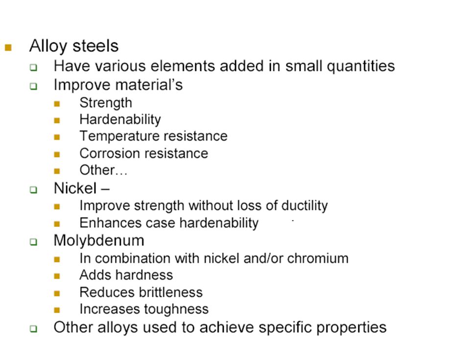
Many of the properties of steel are affected by: Carbon content Impurities (sulfur, phosphorus and slag) Addition of alloys such as chromium Heat treatment
 Addition of alloys such as chromium. Heat treatment.")
6
HISTORY OF METALS 86 Metals known today
Only 24 discovered before 19th century Earliest metals were gold (6000BC) and copper (4200BC) Seven Origin were: Gold( 6000BC), Copper( 4200BC), Silver (4000BC), Lead (3500BC), Tin (1750BC), Smelted Iron (1500BC) and Mercury ( 750BC)
 and copper (4200BC) Seven Origin were: Gold( 6000BC), Copper( 4200BC), Silver (4000BC), Lead (3500BC), Tin (1750BC), Smelted Iron (1500BC) and Mercury ( 750BC)")
7
HISTORY OF METALS Although several metals occur in the earth’s crust in their native state, the early civilizations learned to process ores -- usually metal sulfides or oxides -- by reduction or oxidation processes at elevated temperatures. At first, this probably happened by accident, when these ores were dropped into campfires. By smelting tin ores with copper ores a new kind of “copper” was produced that was stronger and easier to cast.. This was discovery of bronze.

8
Melting of Materials Melting point ( c ) Aluminium 659 Silver 961 Gold 1063 Copper 1083 Iron 1520 Cast iron 1093 Steel 1371 Carbon 3500

9
Steel Percent of carbon in Iron
Iron with controlled amounts of carbon. Steels are classified by their carbon content. Designation Wrought Iron Low Carbon Medium Carbon High Carbon Very High Carbon Gray Cast Iron % Carbon Steel

10
Carbon concentration, wt% C Eutectic
Fe 3 C cementite 1600 1400 1200 1000 800 6 00 4 1 2 5 6.7 L g austenite +L +Fe a + L+Fe d (Fe) Carbon concentration, wt% C Eutectic Eutectoid 0.77 4.30 727°C 1148°C T(°C) Steel generally has less than about 0.7% C, but can have up to 1.4 (2.11theory) % C.
 Carbon concentration, wt% C. Eutectic. Eutectoid °C. 1148°C. T(°C) Steel generally has less than about 0.7% C, but can have up to 1.4 (2.11theory) % C.")
11
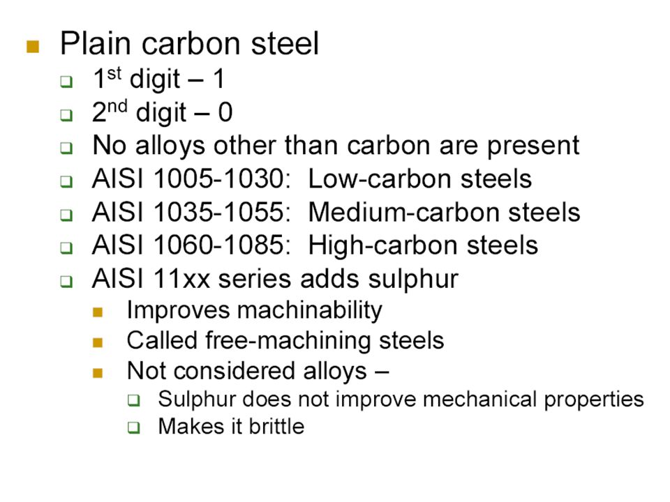
Summary: Steels Low-Carbon Steels
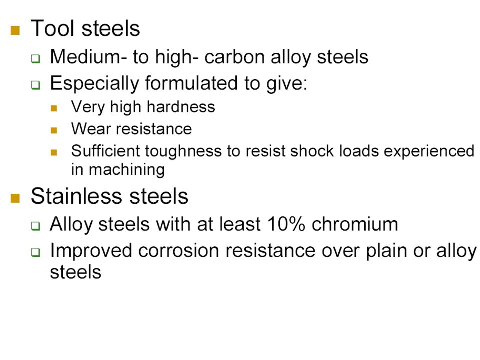
Properties: nonresponsive to heat treatments; relatively soft and weak; machinable and weldable. Typical applications: automobile bodies, structural shapes, pipelines, buildings, bridges, and tin cans. Medium-Carbon Steels Properties: heat treatable, relatively large combinations of mechanical characteristics. Typical applications: railway wheels and tracks, gears, crankshafts, and machine parts. High-Carbon Steels Properties: hard, strong, and relatively brittle. Typical applications: chisels, hammers, knives, and hacksaw blades. High-Alloy Steels (Stainless and Tool) Properties: hard and wear resistant; resistant to corrosion in a large variety of environments. Typical applications: cutting tools, drills, cutlery, food processing, and surgical tools.
 Properties: hard and wear resistant; resistant to corrosion in a large variety of environments. Typical applications: cutting tools, drills, cutlery, food processing, and surgical tools.")
12
Standards Designation Equivalent of Tool Steels ---
AISI American Iron & Steel Institute JIS Japanese Industrial Standards DIN Deutsches Institut für Normung (German Standards Institute) SS Svensk Standard (Swedish Standard) BS British Standards
 SS. Svensk Standard. (Swedish Standard) BS. British Standards.")
17
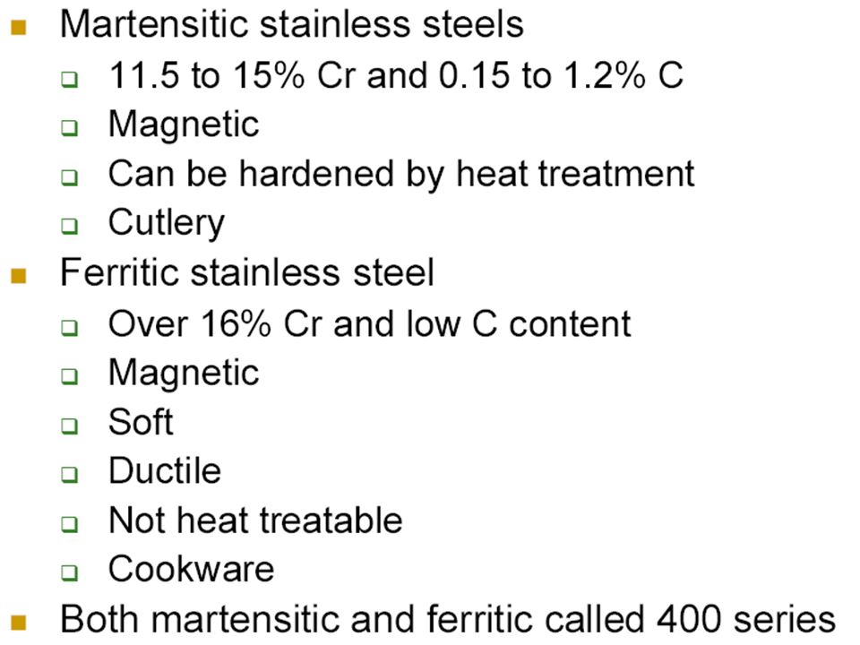
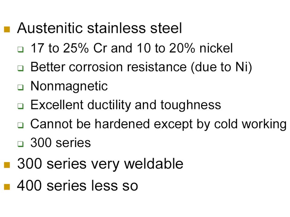
Stainless Steel >10% Chromium
May also contain large amounts of nickel The austenite structure survives at room temperature Makes the steel especially corrosion resistant Non magnetic-Only martensitic stainless

20
Metal Cutting 1.Traditional Machine Turning Milling etc.
2. Non-traditional Machine Laser, EDM etc. Chip

21
Turning

22
Propose The operational uses and parameters,
The general layout of controls, accessories, associated tooling It takes a considerable time to become a skilled lathe operator and to possess all the skill of hand that goes with it. Therefore it is not expected that you will be manually skilled on completion of the module but you will have gained intellectually, by practical involvement, some skill of hand will be achieved.

23
apron Centre Lathe

24
Bed - the main frame,H-beam on 2 V-support It has guideways for carriage to slide easily lengthwise Headstock The spindle is driven through the gearbox Tailstock - Quill- Lath center, Tooling reference Drill

25
A Plain Lath Center Quill Tailstock Chuck

26
Producing a Flat Surface
Producing a Cylindrical Surface Producing a Flat Surface

27
Figure 2c. Taper Turning Figure 2e. Radius Turning Attachment

28
Cutting Tools The tool used in a lathe is known as a single point cutting tool. It has one cutting edge or point whereas a drill has two cutting edges and a file has numerous points or teeth. The lathe tool shears the metal rather than cuts as will be seen later and it can only do so if there is relative motion between the tool and the workpiece. For example, the work is rotating and the tool is moved into its path such that it forms an obstruction and shearing takes place. Of course the amount of movement is of paramount importance - too much at once could for instance result in breakage of the tool. The type and design of the tools selected will depend on the job in hand, the machining operation selected and the material to be cut. The correct tool especially the various face angles are essential if the operation is to be done in a cost-effective (i.e. productive) way. The tools used in a lathe are various, some of which are shown in figure 3. The range of cutting tool types is extensive and a few examples only are shown in this handout. Nonetheless you should take every opportunity to look deeper into the types of tools available
 way. The tools used in a lathe are various, some of which are shown in figure 3. The range of cutting tool types is extensive and a few examples only are shown in this handout. Nonetheless you should take every opportunity to look deeper into the types of tools available.")
31
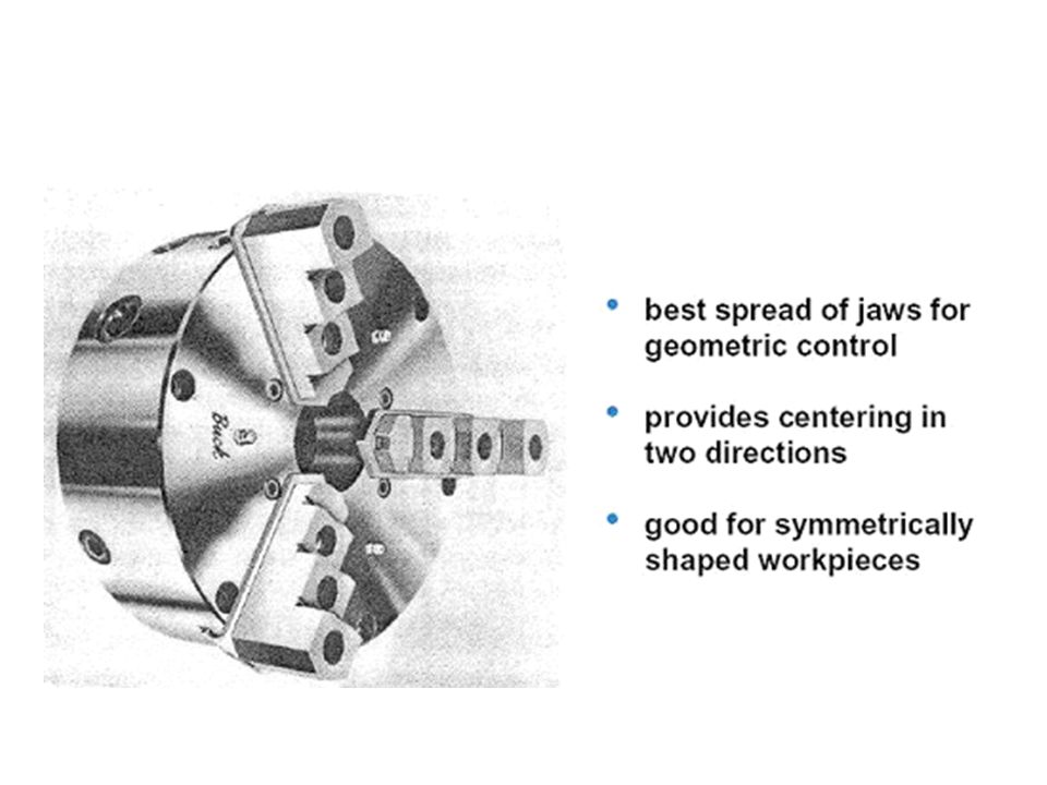
CHUCK JAW Bevel pinion Bevel gear with spiral scroll

32
Face Plate Counterweght Workpiece

33
Face plate Dog Workpiece Lathe Center

34
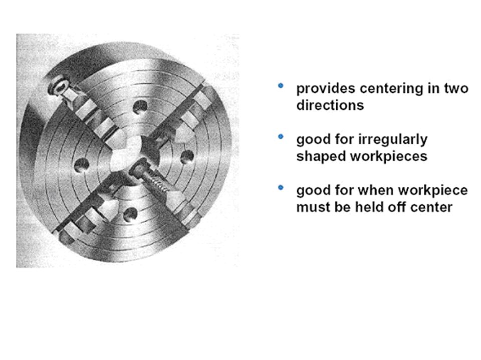
Steady rest Three Adjustable Jaws

35
Basic Metal Cutting Theory
RAKE Relief The usual conception of cutting suggests clearing the substance apart with a thin knife or wedge. When metal is cut the action is rather different and although the tool will always be wedge shaped in the cutting area and the cutting edge should always be sharp the wedge angle will be far too great for it to be considered knife shaped. Consequently a shearing action takes place when the work moves against the tool. Figure 4 shows a tool being moved against a fixed work piece. When the cut is in progress the chip presses heavily on the top face of the tool and continuous shearing takes place across the shear plane AB. Although the Figure shows a tool working in the horizontal plane with the workpiece stationary, the same action takes place with the work piece revolving and the tool stationary.

36
Main Features of a Single Point Cutting Tool
Tool Angles There are three angle. important angles in the construction of a cutting tool rake angle, clearance angle and plan approach

37
Rake Angle The larger the rake angle, the smaller the cutting force on the tool, A large rake angle will improve cutting action, but would lead to early tool failure A compromise must therefore be made between adequate strength and good cutting action. Clearance Angle Clearance should be kept to a minimum, as excessive clearance angle will not improve cutting efficiency and will merely weaken the tool.

38
Characteristics of Tool Material
Hot Hardness the ability to retain its hardness at high temperatures. Strength and Resistance to Shock At the start of a cut the first bite of the tool into the work results in considerable shock Low Coefficient of Friction . Hot Hardness This means Strength and Resistance to Shock loading on the tool. It must obviously be strong enough to withstand it. Low Coefficient of Friction The tool rubbing against the workpiece and the chip rubbing on the top face of the tool produce heat which must be kept to a minimum.

39
Tool Materials in Common Use
High Carbon Steel Contains % carbon with some addition of chromium and tungsten to improve wear resistance. The steel begins to lose its hardness at about 250° C, and is not favoured for modern machining operations where high speeds and heavy cuts are usually employed. High Speed Steel (H.S.S.) Steel, which has a hot hardness value of about 600° C, commonly used for single point and multi point cutting tools Cemented Carbides (WC-Co) An extremely hard material made from tungsten powder. Carbide tools are usually used in the form of brazed or clamped tips HSS may be readily machined using carbide tipped tool. High cutting speeds may be used and materials difficult to cut with HSS High Carbon Steel High Speed Steel (H.S.S.) Cemented Carbides
 Steel, which has a hot hardness value of about 600° C, commonly used for single point and multi point cutting tools. Cemented Carbides (WC-Co) An extremely hard material made from tungsten powder. Carbide tools are usually used in the form of brazed or clamped tips. HSS may be readily machined using carbide tipped tool. High cutting speeds may be used and materials difficult to cut with HSS. High Carbon Steel. High Speed Steel (H.S.S.) Cemented Carbides.")
41
Blade material and major uses
Carbon steel, steel alloy Slow cutting High-speed steel General cutting, difficult-to-cut material Coated super-hard alloys General cutting Ceramics High-speed cutting finishing cuts Polycrystalline Diamond Non-ferrous alloy, non-metal material cutting Sintered cubic boron nitride (CBN) Super-hard alloy, quenched steel, finish cut
 Super-hard alloy, quenched steel, finish cut.")
42
Coating Materials for Cutting tool
WC-Co TiC or TiN or TiCN, Al2O3 PCD Polycrystalline Diamond CBN Cubic Boron Nitride

44
CERMET Ceramic+metal

45
Chip Formation & Chip Breaker
material & cutting conditions These conditions include the type of tool used tool, rate of cutting condition of the machine and the use or absence of a cutting fluid.

46
Continuous Chip - The chip leaves tools a long ribbon
-common when cutting most ductile materials such as mild steel, copper and Aluminium. Ideal Chip It is associated with good tool angles, correct speeds and feeds, and the use of cutting fluid. . Chip Formation & Chip Breaker The type of chip produced depends on the material being machined and the cutting conditions at the time. These conditions include the type of tool used tool, rate of cutting condition of the machine and the use or absence of a cutting fluid. Continuous Chip This leaves the tool as a long ribbon and is common when cutting most ductile materials such as mild steel, copper and Aluminium. It is associated with good tool angles, correct speeds and feeds, and the use of cutting fluid.

47
Discontinuous Chip -resulted from cutting brittle metals such as cast iron and cast brass with tools having small rake angles. There is nothing wrong with this type of chip in these circumstances Discontinuous Chip

48
Continuous Chip with Builtup Edge (BUE)
This is a chip to be avoided and is caused by small particles from the workpiece becoming welded to the tool face under high pressure and heat. The phenomenon results in a poor finish and damage to the tool. It can be minimised or prevented by using light cuts at higher speeds with an appropriate cutting lubricant Continuous Chip with Builtup Edge

49
Cutting Speed Where: N = Spindle Speed (RPM) CS = Cutting Speed of Metal (m/min) d = Diameter of Workpiece 10. Cutting Speed & Feed As you proceed to the process of metal cutting, the relative `speed' of work piece rotation and `feed' rates of the cutting tool coupled to the material to be cut must be given your serious attention. This relationship is of paramount importance if items are to be manufactured in a cost-effective way in the minimum time, in accordance with the laid down specifications for quality of surface finish and accuracy. You, as a potential supervisory / management level engineer, must take particular note of these important parameters and ensure that you gain a fundamental understanding of factors involved All materials have an optimum Cutting Speed and it is defined as the speed at which a point on the surface of the work passes the cutting edge or point of the tool and is normally given in meters/min. To calculate the spindle Speed required,

50
Cutting Speed All materials have an optimum Cutting Speed and it is defined as the speed at which a point on the surface of the work passes the cutting edge or point of the tool and is normally given in meters/min. To calculate the spindle Speed required, Where: N = Spindle Speed (RPM) CS = Cutting Speed of Metal (m/min) d = Diameter of Workpiece Table 2 shows the cutting speed recommended for some common metals. It may be possible to exceed these speeds for light finishing cuts. For heavy cuts they should be reduced.
 CS = Cutting Speed of Metal (m/min) d = Diameter of Workpiece. Table 2 shows the cutting speed recommended for some common metals. It may be possible to exceed these speeds for light finishing cuts. For heavy cuts they should be reduced.")
51
Feed The term `feed' is used to describe the distance the tool moves per revolution of the workpiece and depends largely on the surface finish required. For roughing out a soft material a feed of up to 0.25 mm per revolution may be used. With tougher materials this should be reduced to a maximum of 0.10 mm/rev. Finishing requires a finer feed then what is recommended.

52
Exercise A cylindrical workpart 200 mm in diameter and 700 mm long is to be turned in an engine lathe. Cutting speed = 2.30 m/s, feed = 0.32 mm/rev, and depth of cut = 1.80 mm. Determine (a) cutting time, and (b) metal removal rate.
 cutting. time, and (b) metal removal rate.")
53
Milling

54
Types of Milling Machine
Most of the milling machine are constructed of ¡¥column and knee¡¦ structure and they are classified into two main types namely Horizontal Milling Machine and Vertical Milling Machine. The name Horizontal or Vertical is given to the machine by virtue of its spindle axis. Horizontal machines can be further classified into Plain Horizontal and Universal Milling Machine. The main difference between the two is that the table of an Universal Milling Machine can be set at an angle for helical milling while the table of a Plain Horizontal Milling Machine is not. Vertical Milling Machine Figure 3 shows a vertical milling machine which is of similar construction to a horizontal milling machine except that the spindle is mounted in the vertical position. Its additional features are :- a. Milling head The milling head consisting the spindle, the motor, and the feed control unit is mounted on a swivel base such that it can be set at any angle to the table. b. Ram The ram on which the milling head is attached can be positioned forward and backward along the slideway on the top of the column Horizontal Vertical

55
Side and Face Cutters Slitting Saw
Slab Mills For heavy cutting of large and flat surfaces Side and Face Cutters Slitting Saw

56
End mill Cutting tools for Vertical Milling a. End Mills
Rough Cut End Mills For rapid metal removal. Cutting tools for Vertical Milling a. End Mills Commonly used for facing, slotting and profile milling. Figure 7. End Mill b. Rough Cut End Mills For rapid metal removal. Figure 8. Rough Cut End Mill c. Slot Drills For producing pockets without drilling a hole before hand. Figure 9. Slot Drill d. Face Milling Cutters For heavy cutting. End Mill

57
Slot Drill Face Milling Cutters

58
INSERT ENDMILL INSERT ENDMILL

59
Insert Seat

60
Ballnose

61
Spindle Speed Spindle speed in (R.P.M.) where --
N = R.P.M. of the cutter CS = Linear Cutting Speed of the material in m/min. ( see table 1 ) d = Diameter of cutter in mm
 d = Diameter of cutter in mm.")
62
Feed Rate Feed rate (F) is defined as the rate of travel of the workpiece in mm/min. F = f . u . N where -- F = table feed in mm/min f = Chip load per tooth (mm)( see table 1 ) u = number of teeth of cutter N = R.P.M. of the cutter
( see table 1 ) u = number of teeth of cutter N = R.P.M. of the cutter.")
63
F = f . u . N Table 1

64
Depth of Cut Depth of cut is directly related to the efficiency of the cutting process. For a certain type of cutter, a typical range of cut will be recommended by the supplier. The deeper the cut the faster will be the production rate. Yet, it still depends on the strength of the cutter and the material to be cut.

65
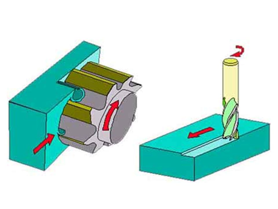
Feed Direction Up Cut Down Cut,Climb Milling
Up Cut MillingIn up cut milling, the cutter rotates in a direction opposite to the table feed as illustrated in figure 14. It is conventionally used in most milling operations because the backlash between the leadscrew and the nut of the machine table can be eliminated. Figure 14. Up Cut Milling b. Down Cut Milling In down cut milling, the cutter rotates in the same direction as the table feed as illustrated in figure 15. This method is also known as and can only be used on machines equipped with a backlash eliminator or on a CNC milling machine. This method, when properly treated, will require less power in feeding the table and give a better surface finish on the workpiece. direction opposite to the table. conventional milling Backlash CNC milling machine. Require less power in feeding the table Give a better surface finish on the workpiece.

68
Introduction Milling machine is one of the most versatile conventional machine tools with a wide range of metal cutting capability. Many complicated operations such as indexing, gang milling, and straddle milling etc. can be carried out on a milling machine. This training module is intended to give you a good appreciation on the type of milling machines and the various types of milling processes. Emphasis is placed on its industrial applications, operations, and the selection of appropriate cutting tools. On completion of this module, you will acquire some of these techniques from the training exercises as illustrated in figure 1. However, to gain maximum benefit, you are strongly advised to make yourself familiar with the following notes before undertaking the training activities, and to have a good interaction between yourself and the staff in charge of your training. Assessment of your training will be based on a combination of your skill and attitude in getting the work done.

69
Forming cutting tool T-Slot

70
Gear Cutting INDEXING HEAD

71
Milling Processes Milling is a metal removal process by means of using a rotating cutter having one or more cutting teeth as illustrated in figure 13. Cutting action is carried out by feeding the workpiece against the rotating cutter. Thus, the spindle speed, the table feed, the depth of cut, and the rotating direction of the cutter become the main parameters of the process. Good results can only be achieved with a well balanced settings of these parameters

72
Cutting fluid (Coolant)
Functions; Reduce the temp. Reduce friction. Wash away chips Improve surface finish Increase tool life Help prevent BUE

73
Cutting fluids in common use
Water encourages rusting Soluble Oils Adding emulsifying agents. These fluids have average lubricating abilities and good cooling properties. There are many forms of soluble oil in the market and the suppliers instruction should be followed regarding the proportions of the `mix'. Mineral Oils They are used for heavier cutting operations Mineral oils are very suitable for steels but should not be used on copper or its alloys since it has a corrosive effect Vegetable Oils They are good lubricants but are of little used since they are liable to decompose and smell badly. Water . Soluble Oils Oil will not dissolve in water but can be made to form an intimate mixture or emulsion by adding emulsifying agents. The oil is then suspended in the water in the form of tiny droplets. These fluids have average lubricating abilities and good cooling properties. Soluble oils are suitable for light cutting operations on general purpose machines where high rates of metal removal are often not of prime importance. There are many forms of soluble oil in the market and the suppliers instruction should be followed regarding the proportions of the `mix'. Mineral Oils Vegetable Oils

74
Work Holding Method vice
In the machining of a complex component, it is usually started off with the milling of a rectangular block. To ensure that each surface of the rectangular block is perpendicular to its neighbouring surfaces, the following points should be noted:- The jaws and the workpiece must be free from burrs, chips, and cutting fluid. Smaller workpiece should be supported by parallel bars to provide the supporting datum. Round bar must be placed between the workpiece and the movable jaw to ensure that the workpiece is in perfect contact with the fix jaw. The vice handle should be tightened by hand to avoid over clamping of the workpiece as well as the vice. Hide face hammer should be used to assure that the workpiece is in perfect contact with the supporting base. On completion of the milling of the first face, the workpiece should be unloaded, deburred, and cleaned before the next operation. To machine the second and the third faces, the workpiece should be clamped with its preceding machined surface facing against the fix jaw of the vice. Similar clamping method can be applied in the machining of the fourth face. Yet it can also be clamped on the vice without the round bar. Both ends of the workpiece can be machined with the periphery flutes of the cutter using up cut milling as shown in figure 23.

75
Dial gauge The accuracy of dial 0.010 mm.
principle of dial indicator () is that the linear mechanical movement of the stylus is magnified and transferred to the rotation of pointer as shown in figure 12. The accuracy of dial mm. It is usually used for calibration of machine.
 is that the linear mechanical movement of the stylus is magnified and transferred to the rotation of pointer as shown in figure 12. The accuracy of dial mm. It is usually used for calibration of machine.")
76
Drilling is the process of cutting holes in metals by using a drilling machine as shown in figure 27. Drills are the tools used to cut away fine shavings of material as the drill advances in a rotational motion through the material. 6a. Twist Drill The twist drill (figure 28) is made from High Speed Steel, tempered to give maximum hardness throughout the parallel cutting portion. Flutes are incorporated to carry away the chips of metal and the outside surface is relieved to produce a cutting edge along the leading side of each flute. The point of the drill is ground to an angle of 59¢X to the centre line to give two equal cutting edges, and each side is ground back to give " relief " of about 12¢X to each cutting edge as shown in figure 29. It is very important that drill points are central and that the lip angles are equal and that the cutting edges are unchipped and the clearance angle correct. To obtain this state and ensure correct angles it is important that drills are ground in a grinding machine.
 is made from High Speed Steel, tempered to give maximum hardness throughout the parallel cutting portion. Flutes are incorporated to carry away the chips of metal and the outside surface is relieved to produce a cutting edge along the leading side of each flute. The point of the drill is ground to an angle of 59¢X to the centre line to give two equal cutting edges, and each side is ground back to give relief of about 12¢X to each cutting edge as shown in figure 29. It is very important that drill points are central and that the lip angles are equal and that the cutting edges are unchipped and the clearance angle correct. To obtain this state and ensure correct angles it is important that drills are ground in a grinding machine.")
77
Tools Twist Drill: Shank Body Point
Shank: part that is clamped in the driving machine. Body: Includes the flutes, helical grooves, of the twist drill. Purpose of flutes: Allow coolant to flow to the cutting edges. Allow chips to flow out of the work piece. Point: The edge of the twist drill that contains the lips. Point angles: Conventional: used for general drilling processes. Low angle (60-90): used for non ferrous materials. Flat angle (135): used for hard materials.
: used for non ferrous materials. Flat angle (135): used for hard materials.")
78
Center Drill Prick Before drill

79
COUNTERSINK&BORE

80
Collet

81
Tightening Nut Collet

82
Shank

83
Shank of Holder

84
TAP Inside Thread

85
DIE Outside Thread

86
Reamer Functions of reamer are to control the diameter of a hole
to improve the internal surface finish to improve the roundness of the hole Reamer Functions of reamer are to control the diameter of a hole to improve the internal surface finish to improve the roundness of the hole Reamer is made of hardened High Carbon Steel or High Speed Steel. It is classified into hand reamer and machine reamer. 1. Hand Reamer Hand reamer (figure 33) has two types of flutes: - straight and spiral flutes. The spiral flutes hand reamer has a left hand spiral flutes. The purpose of the design is to prevent the reamer "screw in" the hole. Figure 35. Hand Reamer 2. Machine Reamer Machine reamer (figure 34) has a straight shank or taper shank (Morse taper). The taper shank can fit directly into the spindle of a machine while the straight shank is hold by the collet. Figure 35. Machine Reamer 3. Expanding Reamer/Adjustable Reamer The cutting diameter can be slightly varied by adjusting an inner taper against the loss cutting blades as shown in figure 35. This type is used primarily for repetitive work to maintain a consistent size throughout. Figure 35. Adjustable Reamer 4. Safety, Precautions & Operation in Reaming Care the sharp cutting edge especially in handling. The amount of material to be removed by a reamer should be as small as possible, approximately 2-4% of diameter. Reamer must only be turned in one direction, both cutting and removing the tools, otherwise the tool may jam. Lubricant oil should be used except when cutting cast iron and brass. Reaming can enlarge the size of hole, but cannot correct the position error in drilling.
 has two types of flutes: - straight and spiral flutes. The spiral flutes hand reamer has a left hand spiral flutes. The purpose of the design is to prevent the reamer screw in the hole. Figure 35. Hand Reamer. 2. Machine Reamer. Machine reamer (figure 34) has a straight shank or taper shank (Morse taper). The taper shank can fit directly into the spindle of a machine while the straight shank is hold by the collet. Figure 35. Machine Reamer 3. Expanding Reamer/Adjustable Reamer. The cutting diameter can be slightly varied by adjusting an inner taper against the loss cutting blades as shown in figure 35. This type is used primarily for repetitive work to maintain a consistent size throughout. Figure 35. Adjustable Reamer. 4. Safety, Precautions & Operation in Reaming. Care the sharp cutting edge especially in handling. The amount of material to be removed by a reamer should be as small as possible, approximately 2-4% of diameter. Reamer must only be turned in one direction, both cutting and removing the tools, otherwise the tool may jam. Lubricant oil should be used except when cutting cast iron and brass. Reaming can enlarge the size of hole, but cannot correct the position error in drilling.")
87
12 Drill 12.00mm Hole mm - 0.10 Ream 12.00mm Hole mm - 0.00

Similar presentations


 General Introduction Dr. Ahmed Abou El-Wafa.>")


 Nonferrous.>")
