Download presentation
Presentation is loading. Please wait.

1
Module 12 MXL DCB <Place supporting graphic here>
Welcome to the Dell 12G version of the PowerEdge M1000e training course. This training provides an overview of the components and features of the Dell PowerEdge M1000e Blade Server enclosure. 12-1

2
Module Objectives: Describe DCB
Describe each of the four DCB protocols Enable Tagging on the array using one of three methods Configure the MXL for DCB Use The Broadcom utility to configure Network Partitioning for Microsoft Servers 12-2

3
DCB

4
What is DCB? Data Center Bridging (DCB) –Is a set IEEE Ethernet enhancements that provide data centers with the ability to converged network traffic into multiple traffic types, like (LAN), server, and storage traffic. Instead of deploying an Ethernet network for LAN traffic, and additional network for storage only one DCB-enabled network is required in a data center. The MXL switch supports a unified fabric and the ability to consolidate multiple network infrastructures . The server in this network uses a single input/output (I/O) device called a converged network adapter (CNA) to support DCB. A CNA is a computer input/output device that combines the functionality of a host bus adapter (HBA) with a network interface controller (NIC). Multiple adapters on different devices for several traffic types are no longer required. Data Center Bridging (DCB) refers to a set of IEEE Ethernet enhancements that provide data centers with a single, robust, converged network to support multiple traffic types, including local area network (LAN), server, and storage traffic. Through network consolidation, DCB results in reduced operational cost, simplified management, and easy scalability by avoiding the need to deploy separate application-specific networks. For example, instead of deploying an Ethernet network for LAN traffic, additional storage area networks (SANs) to ensure lossless fibre-channel traffic, and a separate InfiniBand network for high-performance inter-processor computing within server clusters, only one DCB-enabled network is required in a data center. The Dell Force10 switches that support a unified fabric and consolidate multiple network infrastructures use a single input/output (I/O) device called a converged network adapter (CNA). A CNA is a computer input/output device that combines the functionality of a host bus adapter (HBA) with a network interface controller (NIC). Multiple adapters on different devices for several traffic types are no longer required. 12-4
 –Is a set IEEE Ethernet enhancements that provide data centers with the ability to converged network traffic into multiple traffic types, like (LAN), server, and storage traffic. Instead of deploying an Ethernet network for LAN traffic, and additional network for storage only one DCB-enabled network is required in a data center. The MXL switch supports a unified fabric and the ability to consolidate multiple network infrastructures . The server in this network uses a single input/output (I/O) device called a converged network adapter (CNA) to support DCB. A CNA is a computer input/output device that combines the functionality of a host bus adapter (HBA) with a network interface controller (NIC). Multiple adapters on different devices for several traffic types are no longer required. Data Center Bridging (DCB) refers to a set of IEEE Ethernet enhancements that provide data centers with a single, robust, converged network to support multiple traffic types, including local area network (LAN), server, and storage traffic. Through network consolidation, DCB results in reduced operational cost, simplified management, and easy scalability by avoiding the need to deploy separate application-specific networks. For example, instead of deploying an Ethernet network for LAN traffic, additional storage area networks (SANs) to ensure lossless fibre-channel traffic, and a separate InfiniBand network for high-performance inter-processor computing within server clusters, only one DCB-enabled network is required in a data center. The Dell Force10 switches that support a unified fabric and consolidate multiple network infrastructures use a single input/output (I/O) device called a converged network adapter (CNA). A CNA is a computer input/output device that combines the functionality of a host bus adapter (HBA) with a network interface controller (NIC). Multiple adapters on different devices for several traffic types are no longer required")
5
DCB Protocols To ensure lossless delivery and latency-sensitive scheduling of storage and service traffic and I/O convergence of LAN, storage, and server traffic over a unified fabric, IEEE data center bridging adds the following extensions to a classical Ethernet network: 802.1Qbb - Priority-based Flow Control (PFC) 802.1Qaz - Enhanced Transmission Selection (ETS) 802.1Qau - Congestion Notification Data Center Bridging Exchange (DCBX) protocol 12-5
 802.1Qaz - Enhanced Transmission Selection (ETS) 802.1Qau - Congestion Notification. Data Center Bridging Exchange (DCBX) protocol")
6
Priority Based Flow Control (802.1Qbb)
Each Class needs to be created and priority assigned HALT an individual stream, but NOT all of them! 802.1Qbb (Priority-based Flow Control) 10GE Link Receive buffers dot1p priority queues as virtual transmit queues 7 6 5 4 3 2 1 PFC pauses transmission of priority4 traffic In a data center network, priority-based flow control (PFC) manages large bursts of one traffic type in multiprotocol links so that it does not affect other traffic types and no frames are lost due to congestion. When PFC detects congestion on a queue for a specified priority, it sends a pause frame for the 802.1p priority traffic to the transmitting device. In this way, PFC ensures that large amounts of queued LAN traffic do not cause storage traffic to be dropped, and that storage traffic does not result in high latency for high-performance computing (HPC) traffic between servers. PFC enhances the existing 802.3x pause and 802.1p priority capabilities to enable flow control based on 802.1p priorities (classes of service). Instead of stopping all traffic on a link (as performed by the traditional Ethernet pause mechanism), PFC pauses traffic on a link according to the 802.1p priority set on a traffic type. You can create lossless flows for storage and server traffic while allowing for loss in case of LAN traffic congestion on the same physical interface. The graphic shows how PFC handles traffic congestion by pausing the transmission of incoming traffic with dot1p priority 4. 12-6
 10GE. Link. Receive buffers. dot1p priority queues as virtual transmit queues PFC pauses transmission. of priority4 traffic. In a data center network, priority-based flow control (PFC) manages large bursts of one traffic type in multiprotocol links so that it does not affect other traffic types and no frames are lost due to congestion. When PFC detects congestion on a queue for a specified priority, it sends a pause frame for the 802.1p priority traffic to the transmitting device. In this way, PFC ensures that large amounts of queued LAN traffic do not cause storage traffic to be dropped, and that storage traffic does not result in high latency for high-performance computing (HPC) traffic between servers. PFC enhances the existing 802.3x pause and 802.1p priority capabilities to enable flow control based on 802.1p priorities (classes of service). Instead of stopping all traffic on a link (as performed by the traditional Ethernet pause mechanism), PFC pauses traffic on a link according to the 802.1p priority set on a traffic type. You can create lossless flows for storage and server traffic while allowing for loss in case of. LAN traffic congestion on the same physical interface. The graphic shows how PFC handles traffic congestion by pausing the transmission of incoming traffic with dot1p priority")
7
(Enhanced Transmission Selection)
Enhanced Transmission Selection (802.1Qaz) Allocated bandwidth is based on the class of the traffic. Which will provide a guarantee of bandwidth Actual usage. If not all bandwidth is used it can be shared with other pipes. 802.1Qaz (Enhanced Transmission Selection) t1 5G 4G 1G 3G 10GE Link t2 ETS is used to assign traffic to specific lanes using class of service (CoS) values to identify which lane the traffic belongs to. PFC and ETS together allow administrators to allocate buffers, queues and other resources based on the priority of the application. The result is a predictable, high level of service for business-critical traffic. CoS values are transmitted and discovered using the Link Layer Discovery Protocol (LLDP), and data for the different types of traffic are formatted as Type-Length Values (TLVs). Until recently, administrators could not separate LAN and iSCSI SAN traffic simply because support for iSCSI TLVs were not incorporated into most DCB implementations. Brocade and Dell are the first to provide an end-to-end 10Gb iSCSI SAN that takes full advantage of PFC and ETS. 12-7
 Allocated bandwidth is based on the class of the traffic. Which will provide a guarantee of bandwidth. Actual usage. If not all bandwidth is used it can be shared with other pipes Qaz. (Enhanced Transmission Selection) t1. 5G. 4G. 1G. 3G. 10GE. Link. t2. ETS is used to assign traffic to specific lanes using class of service (CoS) values to identify which lane the traffic belongs to. PFC and ETS together allow administrators to allocate buffers, queues and other resources based on the priority of the application. The result is a predictable, high level of service for business-critical traffic. CoS values are transmitted and discovered using the Link Layer Discovery Protocol (LLDP), and data for the different types of traffic are formatted as Type-Length Values (TLVs). Until recently, administrators could not separate LAN and iSCSI SAN traffic simply because support for iSCSI TLVs were not incorporated into most DCB implementations. Brocade and Dell are the first to provide an end-to-end 10Gb iSCSI SAN that takes full advantage of PFC and ETS")
8
Data Center Bridging compatibility eXchange (DCBX-802.1Qaz)
Built upon LLDP (802.1AB) Neighbors can configure parameters based on TLV exchange Switch will configure the arrays and servers the servers via iSCSI TLV using LLDP 12-8
 Neighbors can configure parameters based on TLV exchange. Switch will configure the arrays and servers the servers via iSCSI TLV using LLDP")
9
Congestion Notification (802.1Qau)
End-to-End Communication between end-points. Tells the end-point to BACK OFF! Congestion Notification allows for an end to end communication to throttle back the sender and adjust the senders output. It will “slow down” the data flow instead of pausing it like “flow control”. 12-9

10
Conformance Dell has published list of companies which integrate iSCSI over DCB into their Switch products storage-infrastructure-and-solutions-team-publications.aspx Components must support the iSCSI TLV. Many companies do not currently support iSCSI TLV with their DCB implementations. Some Brocade switches will support iSCSI TLV. Validated switch list will tell us which switches support this. 12-10

11
DCB implementation Use of VLAN tags
In order to identify priorities, each frame is tagged with a 802.1Q tag VLAN ID is part of the tag hence VLAN ID is required for DCB One VLAN ID for the group and is used for all SAN 10GE interfaces (i.e., not including management network) Switch support CEE/DCB-trunking/converged switchport mode required (differs by vendor) Using DCBX, switch communicates configuration to end-stations 802.1Q is VLAN tagging Converged Enhanced Ethernet = CEE/DCB 12-11
 Switch support. CEE/DCB-trunking/converged switchport mode required (differs by vendor) Using DCBX, switch communicates configuration to end-stations Q is VLAN tagging. Converged Enhanced Ethernet = CEE/DCB")
12
Installation and Setup
Welcome to Group Manager Copyright Dell, Inc. It appears that the storage array has not been configured. Would you like to configure the array now ? (y/n) [n] Please run setup before executing management commands It appears that the storage array has not been configured. Please run setup before executing management commands. CLI> setup def_dcb_vlan_id <<TAB IS YOUR FRIEND>> Group Manager Setup Utility The setup utility establishes the initial network and storage configuration for a storage array and then configures the array as a member of a new or existing group of arrays. NOTE: There is currently no support for setting DCB VLAN ID with the Remote Setup Wizard.
 [n] Please run setup before executing management commands. It appears that the storage array has not been configured. Please run setup before executing management commands. CLI> setup def_dcb_vlan_id 2 <<TAB IS YOUR FRIEND>> Group Manager Setup Utility. The setup utility establishes the initial network and storage. configuration for a storage array and then configures the array. as a member of a new or existing group of arrays. NOTE: There is currently no support for setting DCB VLAN ID with the Remote Setup Wizard.")
13
Create vlan via CLI and GUI
grpparams dcb default-vlan-id or Set grpparams dcb default-vlan-id (GUI or CLI) Set DCB configuration on switch (traffic classes, bandwidth allocation, lossless priorities) Enable DCB for array’s switch ports Remove default VLAN on switch for array’s ports Verify DCB operation on array 12-13
 Set DCB configuration on switch (traffic classes, bandwidth allocation, lossless priorities) Enable DCB for array’s switch ports. Remove default VLAN on switch for array’s ports. Verify DCB operation on array")
14
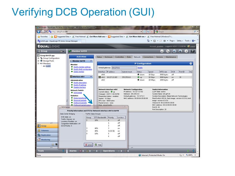
Verifying DCB Operation (GUI)
12-14
15
Disable 802.3x flow control Disable 802.3x flow control on SFP+ ports
FTOS#configure FTOS(conf)#interface range tengigabitethernet 0/1 – 32 FTOS(conf-if-range-te-0/1-32,te-0/41-56)#no flowcontrol rx on tx off FTOS(conf-if-range-te-0/1-32,te-0/41-56)#exit Disable x flow control on QSFP ports FTOS(conf)#interface range fortyGigE 0/33 , fortyGigE 0/37 FTOS(conf-if-range-fo-0/33,fo-0/37)#no flowcontrol rx on tx off FTOS(conf-if-range-fo-0/33,fo-0/37)#exit
#interface range tengigabitethernet 0/1 – 32. FTOS(conf-if-range-te-0/1-32,te-0/41-56)#no flowcontrol rx on tx off. FTOS(conf-if-range-te-0/1-32,te-0/41-56)#exit. Disable x flow control on QSFP ports. FTOS(conf)#interface range fortyGigE 0/33 , fortyGigE 0/37. FTOS(conf-if-range-fo-0/33,fo-0/37)#no flowcontrol rx on tx off. FTOS(conf-if-range-fo-0/33,fo-0/37)#exit.")
16
Enable DCB and reload Enable DCB and reload
If DCB was previously disabled, it must be manually re-enabled. To verify and enable DCB, enter the following commands: Note: This example shows DCB currently disabled and the steps to enable DCB. FTOS#show dcb FTOS#configure FTOS(conf)#dcb enable FTOS(conf)#dcb stack-unit all pfc-buffering pfc-ports 56 pfc-queues 2 FTOS(conf)#exit FTOS#copy running-config startup-config FTOS#reload Note: The switch will reboot.
#dcb enable. FTOS(conf)#dcb stack-unit all pfc-buffering pfc-ports 56 pfc-queues 2. FTOS(conf)#exit. FTOS#copy running-config startup-config. FTOS#reload. Note: The switch will reboot.")
17
Create tagged VLAN for all ports and port-channels
FTOS(conf)#interface vlan VLAN-id Note: You must supply a VLAN id. The valid range is FTOS (conf-if-vl-100)#tagged tengigabitethernet 0/1-32 FTOS (conf-if-vl-100)#tagged tengigabitethernet 0/41-56 FTOS (conf-if-vl-100)#tagged port-channel 1 FTOS (conf-if-vl-100)#exit All ports that will connect to servers or arrays must be set to tagged.
#interface vlan VLAN-id. Note: You must supply a VLAN id. The valid range is FTOS (conf-if-vl-100)#tagged tengigabitethernet 0/1-32. FTOS (conf-if-vl-100)#tagged tengigabitethernet 0/ FTOS (conf-if-vl-100)#tagged port-channel 1. FTOS (conf-if-vl-100)#exit. All ports that will connect to servers or arrays must be set to tagged.")
18
Configure priority groups and policies
Configure priority groups and policies FTOS(conf)#dcb-input pfc FTOS(conf-dcb-in)#pfc priority 4 FTOS(conf-dcb-in)#exit FTOS(conf)#priority-group iSCSI FTOS(conf-pg)#priority-list 4 FTOS(conf-pg)#set-pgid 1 FTOS(conf-pg)#exit FTOS(conf)#priority-group OTHER FTOS(conf-pg)#priority-list 0-3,5-7 FTOS(conf-pg)#set-pgid 2 FTOS(conf)#dcb-output ets FTOS(conf-dcb-out)#priority-group iSCSI qos-policy iSCSI FTOS(conf-dcb-out)#priority-group OTHER qos-policy OTHER FTOS(conf-dcb-out)#exit FTOS (conf)#service-class dynamic dot1p The command “dcb-input pfc” is means to specify which priorities will use priority flow control(pfc). In this example we have specified that priority 4 can use pfc. Next, we are defining a group name and assigning which priorities are associated to that name. Each group has a Priority group ID(pgid). In the examples above the group iSCSI is associated to group 4 with a pgid of 1. The next example is the group OTHER which is associated to priorities 0 thru 3 and 5 thru 7 with a pgid of 2. The command “dcb-output ets” allows you to tie the priority group to a (Quality of Service) qos-policy that will be defined later. In the example above the priority group iSCSI is tied to a qos-poilcy of iSCSI, and the priority group OTHER is tied to a qos-poilcy of OTHER. The last entry “service-class dynamic dot1p” specifies that we are using the 802.1p bits to define how we are classifying traffic.
#dcb-input pfc. FTOS(conf-dcb-in)#pfc priority 4. FTOS(conf-dcb-in)#exit. FTOS(conf)#priority-group iSCSI. FTOS(conf-pg)#priority-list 4. FTOS(conf-pg)#set-pgid 1. FTOS(conf-pg)#exit. FTOS(conf)#priority-group OTHER. FTOS(conf-pg)#priority-list 0-3,5-7. FTOS(conf-pg)#set-pgid 2. FTOS(conf)#dcb-output ets. FTOS(conf-dcb-out)#priority-group iSCSI qos-policy iSCSI. FTOS(conf-dcb-out)#priority-group OTHER qos-policy OTHER. FTOS(conf-dcb-out)#exit. FTOS (conf)#service-class dynamic dot1p. The command dcb-input pfc is means to specify which priorities will use priority flow control(pfc). In this example we have specified that priority 4 can use pfc. Next, we are defining a group name and assigning which priorities are associated to that name. Each group has a Priority group ID(pgid). In the examples above the group iSCSI is associated to group 4 with a pgid of 1. The next example is the group OTHER which is associated to priorities 0 thru 3 and 5 thru 7 with a pgid of 2. The command dcb-output ets allows you to tie the priority group to a (Quality of Service) qos-policy that will be defined later. In the example above the priority group iSCSI is tied to a qos-poilcy of iSCSI, and the priority group OTHER is tied to a qos-poilcy of OTHER. The last entry service-class dynamic dot1p specifies that we are using the 802.1p bits to define how we are classifying traffic.")
19
Configure ETS values Configure ETS values FTOS#configure
FTOS(conf)#qos-policy-output iSCSI ets FTOS(conf-qos-policy-out)#bandwidth-percentage 50 FTOS(conf-qos-policy-out)#exit FTOS(conf)#qos-policy-output OTHER ets Note: the total of all percentages must add up to 100 percent The command “qos-policy-output ets” specifys that there is a qos policy named iSCSI which is used for Enhanced Transmission Selection(ets) which was previously tied to the priority group iSCSI. For instance, this qos policy is then used to specify a guaranteed minimum traffic this priority group is assigned using a percentage, in this example 50%. The policy group OTHER that was previously defined, is also set to 50%. As demonstrated, all percentages must add up to a total of 100 percent.
#qos-policy-output iSCSI ets. FTOS(conf-qos-policy-out)#bandwidth-percentage 50. FTOS(conf-qos-policy-out)#exit. FTOS(conf)#qos-policy-output OTHER ets. Note: the total of all percentages must add up to 100 percent. The command qos-policy-output ets specifys that there is a qos policy named iSCSI which is used for Enhanced Transmission Selection(ets) which was previously tied to the priority group iSCSI. For instance, this qos policy is then used to specify a guaranteed minimum traffic this priority group is assigned using a percentage, in this example 50%. The policy group OTHER that was previously defined, is also set to 50%. As demonstrated, all percentages must add up to a total of 100 percent.")
20
Apply priorities to switch ports
Apply priorities to switch ports FTOS(conf)#interface range tengigabitethernet 0/1 – 32 FTOS(conf-if-range-te-0/1-32,te-0/41-56)#dcb-policy input pfc FTOS(conf-if-range-te-0/1-32,te-0/41-56)#dcb-policy output ets FTOS(conf-if-range-te-0/1-32,te-0/41-56)#protocol lldp FTOS(conf-if-range-te-0/1-32,te-0/41-56-lldp)#exit FTOS(conf-if-range-te-0/1-32,te-0/41-56)#exit FTOS(conf)#interface range fortyGigE 0/33 , fortyGigE 0/37 FTOS(conf-if-range-fo-0/33,fo-0/37)#dcb-policy input pfc FTOS(conf-if-range-fo-0/33,fo-0/37)#dcb-policy output ets FTOS(conf-if-range-fo-0/33,fo-0/37)#exit FTOS(conf)#exit The final piece of the configuration is to tie the pfc and ets policies to the ports. LLDP is also enabled so that DCBX can communicate the configuration to the end-user ports, the array and the servers.
#interface range tengigabitethernet 0/1 – 32. FTOS(conf-if-range-te-0/1-32,te-0/41-56)#dcb-policy input pfc. FTOS(conf-if-range-te-0/1-32,te-0/41-56)#dcb-policy output ets. FTOS(conf-if-range-te-0/1-32,te-0/41-56)#protocol lldp. FTOS(conf-if-range-te-0/1-32,te-0/41-56-lldp)#exit. FTOS(conf-if-range-te-0/1-32,te-0/41-56)#exit. FTOS(conf)#interface range fortyGigE 0/33 , fortyGigE 0/37. FTOS(conf-if-range-fo-0/33,fo-0/37)#dcb-policy input pfc. FTOS(conf-if-range-fo-0/33,fo-0/37)#dcb-policy output ets. FTOS(conf-if-range-fo-0/33,fo-0/37)#exit. FTOS(conf)#exit. The final piece of the configuration is to tie the pfc and ets policies to the ports. LLDP is also enabled so that DCBX can communicate the configuration to the end-user ports, the array and the servers.")
21
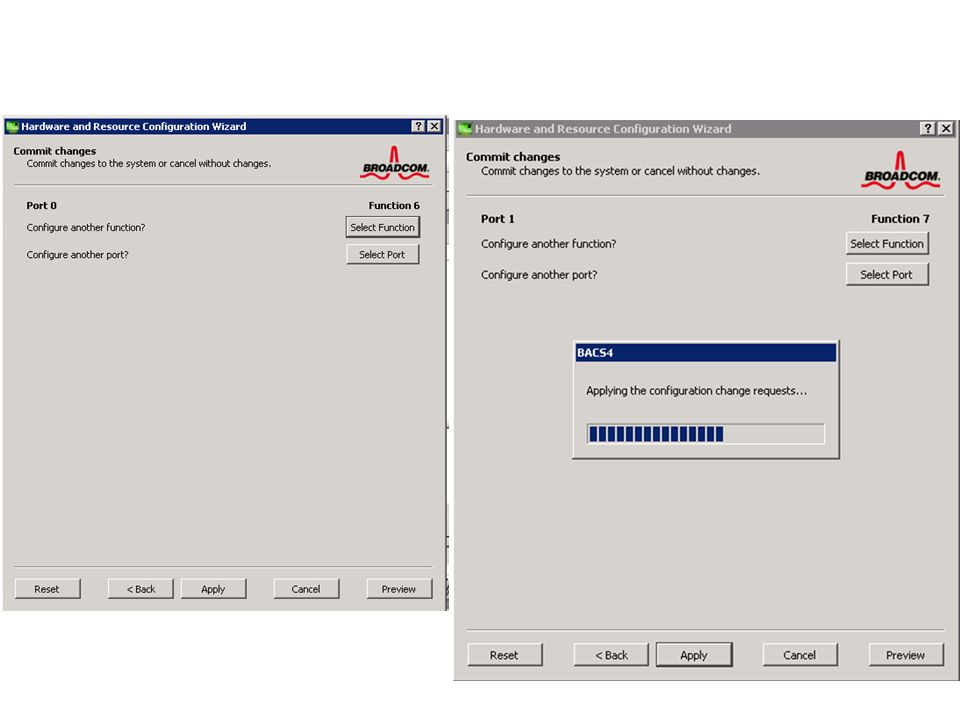
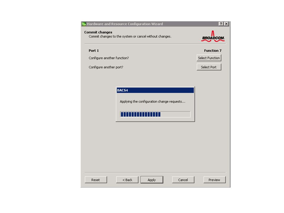
Broadcom Active Control Suite
C.1 Broadcom 57810S DCBX willing mode verification Figure 16 below shows a screen shot from the Broadcom™ Advanced Control Suite application. This is applicable to the Broadcom 57810S Dual-Port 10GbE SFP+ adapter and the Broadcom 57810S Dual-Port 10GbE KR Blade Converged Mezzanine Card on Windows Server 2008 R2 SP1. The parameter “local machine willing” indicates the willing mode state and is enabled by default. 44 BP1044 | Data Center Bridging with Dell EqualLogic iSCSI SANs Figure 16 Initiator willing mode configuration In this figure, the adapter is configured with willing mode enabled by default. Also the local DCBX settings are shown in the default configuration. These settings include the priority and PFC values for FCoE and iSCSI. This also includes the priority groups with their bandwidth allocation and priority mapping. Once the adapter port establishes an operational link with a peer switch port and receives the switch DCBX settings, it will use those settings for DCB operations. The local settings will not be operational at that point. The default local DCBX setting can be changed by overriding them. C.2 Broadcom 57810S iSCSI VLAN configuration The figure below illustrates the VLAN configuration for iSCSI traffic on the adapter port. 45 BP1044 | Data Center Bridging with Dell EqualLogic iSCSI SANs Figure 17 Initiator VLAN ID configuration C.3 Broadcom 57810S DCB configuration verification The image below is the screen shot from the Broadcom Advanced Control Suite application. This is applicable to the Broadcom 57810S Dual-Port 10GbE SFP+ adapter and the Broadcom 57810S Dual-Port 10GbE KR Blade Converged Mezzanine Card on Windows Server 2008 R2 SP1. The DCB parameters shown are the values advertised by the switch peer and accepted by the NIC port. It also indicates the DCB operational state for each feature. Figure 18 DCBX operation state and configuration verification The local and remote DCBX settings are illustrated in the advanced section illustrated in figure below. 46 BP1044 | Data Center Bridging with Dell EqualLogic iSCSI SANs Figure 19 Advanced DCB operation state and configuration verification Broadcom Active Control Suite Broadcom 57810S DCBX willing mode verification Here is a screen shot from the Broadcom™ Advanced Control Suite application. This is applicable to the Broadcom 57810S Dual-Port 10GbE SFP+ adapter and the Broadcom 57810S Dual-Port 10GbE KR Blade Converged Mezzanine Card on Windows Server 2008 R2 SP1. 12-21

22
Broadcom Active Control Suite

25
Broadcom 57810S iSCSI VLAN configuration
Here is the VLAN configuration for iSCSI traffic on the adapter port. Initiator VLAN ID configuration

26
DCBX operation state and configuration verification
The DCB parameters shown are the values advertised by the switch peer and accepted by the NIC port. It also indicates the DCB operational state for each feature.

27
Module Summary Now that you have completed this module you should be able to: Describe DCB Describe each of the four DCB protocols Enable Tagging on the array using one of the three methods Configure the MXL for DCB Use The Broadcom utility to configure Network Partitioning for Microsoft Servers

28
Lab Lab 12 – Converged Infrastructure Solution
Configure the array for DCB and VLAN tagging Configure the MXL switch for DCB Use the Broadcom Utility to configure Network Partitioning

29
Questions?

Similar presentations


. Switches, also known as switching hubs, have become an increasingly important part of our networking today, because when working with hubs,>")


 Chapter Two Deploying Windows Servers.>")

. VLANs provide greater opportunities to manage the flow of traffic on.>")