Download presentation
Presentation is loading. Please wait.

1
Specifying and Sizing Control Valves A design equation used for sizing control valves relates valve lift to the actual flow rate q by means of the valve coefficient C v, the proportionality factor that depends predominantly on valve size or capacity: 1

2
2 Here q is the flow rate, is the flow characteristic, is the pressure drop across the valve, and g s is the specific gravity of the fluid. This relation is valid for nonflashing fluids. Specification of the valve size is dependent on the so-called valve characteristic f. Three control valve characteristics are mainly used. For a fixed pressure drop across the valve, the flow characteristic is related to the lift, that is, the extent of valve opening, by one of the following relations:

3
Example-1 A pump furnishes a constant head of 40 psi over the entire flow rate range of interest. The heat exchanger pressure drop is 30 psig at 200 gal/min (q d ) and can be assumed to be proportional to q 2. Select the rated C v of the valve and plot the installed characteristic for the following case: Assume specific gravity of fluid as 4 at pumping Temp. A linear valve that is half open at the design flow rate.
 and can be assumed to be proportional to q 2. Select the rated C v of the valve and plot the installed characteristic for the following case: Assume specific gravity of fluid as 4 at pumping Temp. A linear valve that is half open at the design flow rate..")
6
At design flow rate, q d :

8
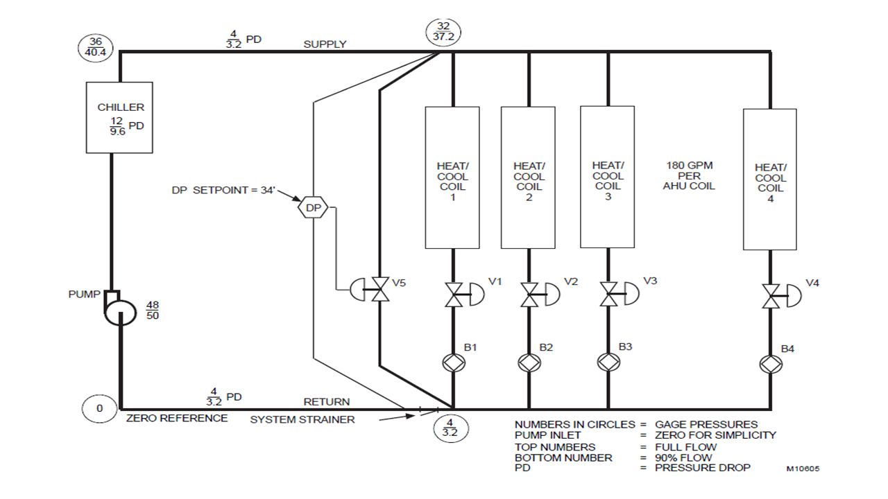
Example-2 A bypass valve is required to prevent flow through the chiller from dropping below 90 percent of design flow. When sizing valves for pump or chiller bypass applications (Fig. below), system conditions that cause the valve to open or close completely must be considered before a pressure drop can be selected. Assume the following: System flow at design, 1000 gpm Pump head at design, 48 ft Pump head at 90 percent flow, 50 ft Pressure across mains at AHU 1 at design flow, 28 ft Chiller pressure drop, 12 ft Chiller piping loop design pressure drop, 8 ft
, system conditions that cause the valve to open or close completely must be considered before a pressure drop can be selected. Assume the following: System flow at design, 1000 gpm Pump head at design, 48 ft Pump head at 90 percent flow, 50 ft Pressure across mains at AHU 1 at design flow, 28 ft Chiller pressure drop, 12 ft Chiller piping loop design pressure drop, 8 ft.")
Similar presentations


 Unit wt. = 62.4 pcf.>")


 2- Empirical modeling (Smith & Corripio, Chapter 7) 3->")


![Assignment No. 1 [Grup 8] Figure below shows a portion of a hydraulic circuit. The pressure point B must be 200 psig when the volume flow rate is 60 gal/min.](/20/6053192/big_thumb.jpg "Assignment No. 1 [Grup 8] Figure below shows a portion of a hydraulic circuit. The pressure point B must be 200 psig when the volume flow rate is 60 gal/min.>")
