Download presentation
Presentation is loading. Please wait.

1
Relationship between Magnitude and Phase (cf. Oppenheim, 1999)
Question: When we only know the magnitude response of an LTI system, can we infer its phase response? In general, knowledge about the magnitude provides no information about the phase. However, for systems described by linear constant coefficient difference equations, i.e., rational system functions, there is some constraint between magnitude and phase. Similarly, if the number of poles and zeros and the phase are known, then, to within a scale factor, there are only a finite number of choices for the magnitude.

2
We consider |H(ejw)|2 expressed as
For the linear constant-coefficient difference-equation case, the system function H(z) is rational in the form where a0 and b0 are real, and {dk} and {ck} are the poles and zeros, respectively.
 is rational in the form. where a0 and b0 are real, and {dk} and {ck} are the poles and zeros, respectively.")
3
Hence, and so Denote that C(z) = H(z)H*(1/z*). Hence, the squared magnitude response is equivalent to the evaluation on the unit circle of the z transform of C(z)
")
4
What can C(z) tell us? For each zero ck of H(z), there is a zero of C(z) at ck and (ck*)1. Similarly, for each pole dk of H(z), there is a pole of C(z) at dk and (dk*)1. Hence, for a difference equation system, the corresponding C(z) satisfies that the poles and zeros of C(z) occur in conjugate reciprocal pairs.
, there is a pole of C(z) at dk and (dk*)1. Hence, for a difference equation system, the corresponding C(z) satisfies that the poles and zeros of C(z) occur in conjugate reciprocal pairs.")
5
One element of each pair is inside the unit circle, then the other (i
One element of each pair is inside the unit circle, then the other (i.e., the conjugate reciprocal) will be outside the unit circle. If H(z) is assumed to correspond to a causal, stable system, then all its poles must lie inside the unit circle. With this constraint, the poles of H(z) can be identified from the poles of C(z). Although the zeros cannot be uniquely identified from the zeros of C(z), we have only a finite number of selections of the zeros. (when M and N are fixed) If we are given |H(ejw)|2, then by replacing ejw by z, we can construct C(z). Hence, knowing only the magnitude information |H(ejw)|2 gives us finite selections of the LTI system with a rational system function, and so the phase response is restricted to these finite selections.
 will be outside the unit circle. If H(z) is assumed to correspond to a causal, stable system, then all its poles must lie inside the unit circle. With this constraint, the poles of H(z) can be identified from the poles of C(z). Although the zeros cannot be uniquely identified from the zeros of C(z), we have only a finite number of selections of the zeros. (when M and N are fixed) If we are given |H(ejw)|2, then by replacing ejw by z, we can construct C(z). Hence, knowing only the magnitude information |H(ejw)|2 gives us finite selections of the LTI system with a rational system function, and so the phase response is restricted to these finite selections.")
6
Example: consider two stable systems with the following system functions:
Now

7
By using the fact that We see that C1(z) = C2(z). Hence, H1(z) and H2(z) have the same C(z) (and thus the same magnitude response). The poles of H1(z) and H2(z) are the same, but the zeros are different. Although the magnitude response are the same, the phase responses of these two systems are different.
 and H2(z) are the same, but the zeros are different. Although the magnitude response are the same, the phase responses of these two systems are different.")
8
H1(z) H2(z) C(z)
 H2(z) C(z)")
9
Pole pairs Zero pairs 1 (P1, P4) (Z1, Z4) 2 (P2, P5) (Z2, Z5) 3
Another Example: Suppose we are given the pole-zero plot for C(z) in the following figure and want to determine the poles and zeros to associate with H(z). The conjugate reciprocal pairs of poles and zeros for which one element of each is associated with H(z) and one with H*(1/z*) are as follows: Pole pairs Zero pairs 1 (P1, P4) (Z1, Z4) 2 (P2, P5) (Z2, Z5) 3 (P3, P6) (Z3, Z6)
 in the following figure and want to determine the poles and zeros to associate with H(z). The conjugate reciprocal pairs of poles and zeros for which one element of each is associated with H(z) and one with H*(1/z*) are as follows: Pole pairs. Zero pairs. 1. (P1, P4) (Z1, Z4) 2. (P2, P5) (Z2, Z5) 3. (P3, P6) (Z3, Z6)")
10
C(z)
")
11
If we assume that H(z) is a stable and causal system, we must choose the poles from each pair that are inside the unite circle. That is, P1, P2, and P3. No such constraint is imposed on the zeros. How can we select the zeros: if we assume that the coefficients of the rational response are all real, i.e., where {ak} and {bk} are real.

12
In this case, the impulse response of the system have real values, and so the frequency response is an even function. The zeros (and poles) either are real or occur in complex conjugate pairs (i.e. symmetric to the real axis). Consequently, the zeros to associate with H(z) are Z3 or Z6 and (Z1, Z2) or (Z4, Z5) Hence, there are a total of four different stable, causal systems with three poles and three zeros. Is there any other systems having the same magnitude responses? If we allow M and N to be varying, there are other systems having the same magnitude response by applying the all-pass system introduced below.
 either are real or occur in complex conjugate pairs (i.e. symmetric to the real axis). Consequently, the zeros to associate with H(z) are. Z3 or Z6. and. (Z1, Z2) or (Z4, Z5) Hence, there are a total of four different stable, causal systems with three poles and three zeros. Is there any other systems having the same magnitude responses If we allow M and N to be varying, there are other systems having the same magnitude response by applying the all-pass system introduced below.")
13
All Pass Systems A stable system function of the following form is referred to as an all-pass system: The frequency response of an all-pass system is independent of the frequency w. Since So

14
The multiplication of two all pass system functions still results in an all pass system. So, all pass systems can be cascaded to construct other all pass systems. The most general form for the system function of an all-pass system is the one with a real-valued impulse response: where A is a positive constant, dk’s are the real poles, and ek’s are the complex poles, |dk|<1 and |ek|<1. Each pole of an all-pass system is paired with a conjugate reciprocal zero. The poles are all inside the unit circle, and so the zeros are outside the unit circle. The magnitude response of a system remains the same by multiplying (cascading) this system with an all-pass system.
 this system with an all-pass system.")
15
Typical pole-zero plot for an all-pass system
H(z)
")
16
Generally, an N-th order all-pass system can also be represented as the following equivalent form:
Properties of the all-pass system: The group delay of a causal rational all-pass system is always positive. All pass systems can be used as compensator for phase (or group-delay) distortion. When the phase response of an IIR filter is not satisfied in the specified band (eg., constant group delay), we can cascade it with an all-pass filter to adjust the phase response.
 distortion. When the phase response of an IIR filter is not satisfied in the specified band (eg., constant group delay), we can cascade it with an all-pass filter to adjust the phase response.")
17
Example of an all-pass system
Log magnitude Phase (principal value) Group delay
 Group delay.")
18
Minimum-phase Systems
We have seen that once the (squared) magnitude response have been specified and the corresponding M and N are fixed for a rational stable and causal system, there are finite choices of the zeros (and also phase responses) of the system. If we impose the additional restriction that the inverse (one with the system function 1/H(z)) also is stable and causal, then we can uniquely determine the zeros. A causal and stable system has an inverse system iff its poles and zeros are all inside the unit circle. Given the squared magnitude response and the corresponding M and N, there is a unique system whose zeros are all inside the unit circle, which is called the minimum-phase system.
 magnitude response have been specified and the corresponding M and N are fixed for a rational stable and causal system, there are finite choices of the zeros (and also phase responses) of the system. If we impose the additional restriction that the inverse (one with the system function 1/H(z)) also is stable and causal, then we can uniquely determine the zeros. A causal and stable system has an inverse system iff its poles and zeros are all inside the unit circle. Given the squared magnitude response and the corresponding M and N, there is a unique system whose zeros are all inside the unit circle, which is called the minimum-phase system.")
19
If we are given the magnitude-squared function:
and know that the system is a minimum-phase system. Then H(z) is uniquely determined and will consist of all the poles and zeros of C(z) that lie inside the unit circle. The minimal-phase system is often followed in filter design when only the magnitude response is specified by the design method used.
 is uniquely determined and will consist of all the poles and zeros of C(z) that lie inside the unit circle. The minimal-phase system is often followed in filter design when only the magnitude response is specified by the design method used.")
20
Eg. for the above C(z), if it is minimum phase, the zeros of H(z) are Z3, Z1, and Z2.
, if it is minimum phase, the zeros of H(z) are Z3, Z1, and Z2.")
21
Why it is called a minimum-phase system?
The minimum phase-lag property: The group delay of the minimum phase system chosen from C(z) is always less than the group delays of the other systems chosen from C(z). Property of minimum-phase and all-pass decomposition: Any rational system can be decomposed into the multiplication of a minimum-phase system and an all-pass system: Let H(z) be any rational system, then we have H(z) = Hmin(z)Hap(z), where Hmin(z) is minimum phase and Hap(z) is all pass.
 is always less than the group delays of the other systems chosen from C(z). Property of minimum-phase and all-pass decomposition: Any rational system can be decomposed into the multiplication of a minimum-phase system and an all-pass system: Let H(z) be any rational system, then we have. H(z) = Hmin(z)Hap(z), where Hmin(z) is minimum phase and Hap(z) is all pass.")
22
To show the above property, suppose that H(z) has only one zero outside the unit circle at z=1/c*, where |c|<1. Then, H(z) can be expressed as H(z) = H1(z)(z1c*), where, by definition, H1(z) is minimum phase. An equivalent expression for H(z) is Since |c|<1, the factor H1(z)(1 cz1) also is minimum phase. The term (z1c*)/(1 cz1) is all-pass. The example can be generalized in a straightforward way to include more zeros outside the unit circle, thereby showing that any rational system function can be expressed by H(z) = Hmin(z)Hap(z).
 can be expressed as H(z) = H1(z)(z1c*), where, by definition, H1(z) is minimum phase. An equivalent expression for H(z) is. Since |c|<1, the factor H1(z)(1 cz1) also is minimum phase. The term (z1c*)/(1 cz1) is all-pass. The example can be generalized in a straightforward way to include more zeros outside the unit circle, thereby showing that any rational system function can be expressed by H(z) = Hmin(z)Hap(z).")
23
From the above, we can see that in the decomposition H(z) = Hmin(z)Hap(z),
The minimum-phase component Hmin(z) contains the poles and zeros of H(z) that lie inside the unit circle, plus zeros that are conjugate reciprocals of the zeros of H(z) that lie outside the unit circle. The all-pass component Hap(z) is comprised of all the zeros of H(z) that lie outside the unit circle, together with poles to cancel the reflected conjugate reciprocal zeros in Hmin(z).
 contains the poles and zeros of H(z) that lie inside the unit circle, plus zeros that are conjugate reciprocals of the zeros of H(z) that lie outside the unit circle. The all-pass component Hap(z) is comprised of all the zeros of H(z) that lie outside the unit circle, together with poles to cancel the reflected conjugate reciprocal zeros in Hmin(z).")
24
Example: consider the stable, causal systems specified by the system function
H(z) has a pole inside the unit circle at z=0.5, but a zero outside at z= 3. We will need to choose the appropriate all-pass system to reflect this zero inside the unit circle. We choose c= (1/3). So, the all pass component will be and the minimum-phase component is then i.e.
 has a pole inside the unit circle at z=0.5, but a zero outside at z= 3. We will need to choose the appropriate all-pass system to reflect this zero inside the unit circle. We choose c= (1/3). So, the all pass component will be. and the minimum-phase component is then. i.e.")
25
Example: consider the distorting system function to be
The pole-zero plot is

26
The corresponding minimum-phase system is obtained by reflecting the zeros that occur at z=1.25ej0.8 to their conjugate reciprocal locations inside the unit circle. Then and the all-pass system that relates Hmin(z) and Hd(z) is
 and Hd(z) is.")
27
Frequency-response Compensation: An application of minimum-phase system.
In many signal-processing contexts, a signal has been distorted by an LTI system with an undesirable frequency response. It may then be of interest to process the distorted signal with a compensation system as follows. Eg., in transmitting signals over a communication channel, if perfect compensation is achieved, then Sc[n] = s[n], i.e., Hc(z) is the inverse of Hd(z), However, if we assume that the distorting system is stable and causal and require the compensating system to be stable and causal too, then perfect compensation is possible only if Hd(z) is a minimum-phase system.
 is the inverse of Hd(z), However, if we assume that the distorting system is stable and causal and require the compensating system to be stable and causal too, then perfect compensation is possible only if Hd(z) is a minimum-phase system.")
28
If Hd(z) is known and can be approximated as a rational system function, but is not minimum phase, we can at least compensate it to an all-pass system that has constant magnitude response, by factorizing it as Hd(z) = Hmin(z)Hap(z), and choosing the compensating filter to be Hc(z) = 1/Hmin(z), By doing so, the overall system is of constant magnitude response, while the phase response is modified to Hap(ejw). Other all-pass filters can be additionally cascaded to transform the phase response to approximate to the desired one in the specified band.
 = Hmin(z)Hap(z), and choosing the compensating filter to be Hc(z) = 1/Hmin(z), By doing so, the overall system is of constant magnitude response, while the phase response is modified to Hap(ejw). Other all-pass filters can be additionally cascaded to transform the phase response to approximate to the desired one in the specified band.")
29
Another property of minimum-phase system
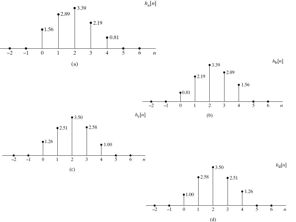
The minimum energy-delay property: In the above example, there are a total of four causal FIR systems with real impulse responses that have the same magnitude response. the minimum-phase one

30
In the following, we show the four impulse responses of these four FIR systems. It will be found that |h[0]| |hmin[0]|, where hmin[n] is the impulse response of the minimum-phase one. 1.56 > 0.81, 1.26, 1.00
![In the following, we show the four impulse responses of these four FIR systems. It will be found that |h[0]| |hmin[0]|, where hmin[n] is the impulse response of the minimum-phase one.](http://slideplayer.com/slide/5976235/20/images/30/In+the+following%2C+we+show+the+four+impulse+responses+of+these+four+FIR+systems.+It+will+be+found+that+%7Ch%5B0%5D%7C+%EF%82%A3+%7Chmin%5B0%5D%7C%2C+where+hmin%5Bn%5D+is+the+impulse+response+of+the+minimum-phase+one..jpg "1.56 > 0.81, 1.26,")
32
In general, it is true that
for any causal, stable sequence h[n] for which It is because that, by the initial-value theorem, without loss of generality, assume that So and hence since |c|<1.

33
By this property, and consider the parseval’s theorem
In general, it can be shown that The partial energy of the minimum-phase system is most concentrated around n=0; i.e., the energy of the minimum-phase system is delayed the least of all systems having the same magnitude response.

34
Summary of all-pass and minimum-phase systems.
Given the magnitude response of a rational system function, the poles can be exactly identified if the system is stable and causal. If the number of zeros, M, is fixed, then there are finite choices of the zeros. If we further restrict the system to be a minimum-phase system, then the zeros are uniquely specified. We can adjust the phase response of a system by cascading it with an all-pass system. Any rational system can be decomposed into a minimum-phase system and an all-pass system.

35
Design of FIR Filter by Windowing
FIR filters are almost entirely restricted to discrete-time implementations. Most techniques for approximating the magnitude response of an FIR system assume a linear phase constraint, thereby avoiding the problem of spectrum factorization that complicates the direct design of IIR filters. The windowing method: consider an ideal desired frequency response (eg. ideal low-pass filter) that can be represented as The simplest way to obtain a causal FIR filter from hd[n] is to define a new system by
 that can be represented as. The simplest way to obtain a causal FIR filter from hd[n] is to define a new system by.")
36
i.e. where w[n] is a rectangular window: Since time domain multiplication implies frequency domain convolution, we have where W(ejw) is the frequency response of w[n].
![i.e. where w[n] is a rectangular window: Since time domain multiplication implies frequency domain convolution, we have.](http://slideplayer.com/slide/5976235/20/images/36/i.e.+where+w%5Bn%5D+is+a+rectangular+window%3A+Since+time+domain+multiplication+implies+frequency+domain+convolution%2C+we+have..jpg "where W(ejw) is the frequency response of w[n].")
37
If w[n] = 1 for all n, W(ejw) is a periodic impulse train with period 2, and therefore H(ejw) = Hd(ejw). If w[n] is chosen so that W(ejw) is concentrated in a narrow band of frequencies around w=0, then H(ejw) will look like Hd(ejw), except where Hd(ejw) change very abruptly. In the case of rectangular window,
![If w[n] = 1 for all n, W(ejw) is a periodic impulse train with period 2, and therefore H(ejw) = Hd(ejw).](http://slideplayer.com/slide/5976235/20/images/37/If+w%5Bn%5D+%3D+1+for+all+n%2C+W%28ejw%29+is+a+periodic+impulse+train+with+period+2%EF%81%B0%2C+and+therefore+H%28ejw%29+%3D+Hd%28ejw%29..jpg "If w[n] is chosen so that W(ejw) is concentrated in a narrow band of frequencies around w=0, then H(ejw) will look like Hd(ejw), except where Hd(ejw) change very abruptly. In the case of rectangular window,")
38
As M increases, the width of the “main lobe” decreases
As M increases, the width of the “main lobe” decreases. The main lobe is usually defined as the region between the first zero-crossings on either side of the origin.

39
Convolution process implied by truncation of the ideal impulse response (i.e., rectangular window)
Typical approximation resulting from windowing the ideal impulse response (rectangular-window case)
")
40
This causes the Gibbs phenomenon, i. e
This causes the Gibbs phenomenon, i.e., as M increases, the maximum amplitude of the oscillation does not approach zero To moderate the Gibbs phenomenon, the use of a less abrupt truncation of the impulse response: tapering the window smoothly to zero at each end. Some commonly used windows: Bartlett (triangular): Hanning: Hamming:
: Hanning: Hamming:")
41
The above windows all satisfy that
In this situation, it can be shown that the resulted filter will be generalized linear phase if the hd[n] is either symmetric (i.e., hd[n]= hd[Mn]) or anti-symmetric (i.e., hd[n]= hd[Mn]).
 or anti-symmetric (i.e., hd[n]= hd[Mn]).")
42
Kaiser window Kaiser found that a near-optimal window could be formed using the zeroth-order modified Bessel function of the first kind. The Kaiser window is defined as where and I0() represents the zeroth-order modified Bessel function of the first kind. In contrast to the other windows, the Kaiser window has two parameters: the loength (M+1) and a shape parameter . Kaiser obtained a pair of formulas that permit the filter designer to predict in advance the values of M and . Consider a low-pass filter. Let the passband cutoff frequency be wp, stopband cutoff frequency be ws, and pass-band distortion be .
 represents the zeroth-order modified Bessel function of the first kind. In contrast to the other windows, the Kaiser window has two parameters: the loength (M+1) and a shape parameter . Kaiser obtained a pair of formulas that permit the filter designer to predict in advance the values of M and . Consider a low-pass filter. Let the passband cutoff frequency be wp, stopband cutoff frequency be ws, and pass-band distortion be .")
43
Denote then the parameters of the Kaiser window can be set as the following to achieve the required specification {wp, ws, }.

Similar presentations


![Z-Transform Fourier Transform z-transform. Z-transform operator: The z-transform operator is seen to transform the sequence x[n] into the function X{z},](/17/5301252/big_thumb.jpg "Z-Transform Fourier Transform z-transform. Z-transform operator: The z-transform operator is seen to transform the sequence x[n] into the function X{z},>")


 Kevin D. Donohue Electrical and Computer Engineering University of Kentucky.>")


