Download presentation
Presentation is loading. Please wait.

1
Department of Computer Eng. Sharif University of Technology Discrete-time signal processing Chapter 5: Transform Analysis of Linear Time- Invariant Systems Content and Figures are from Discrete-Time Signal Processing, 2e by Oppenheim, Shafer and Buck, ©1999-2000 Prentice Hall Inc.

2
5.1Frequency Response of LTI Systems LTI Systems are uniquely determined by their impulse response We can write the input-output relation also in the z-domain Or we can define an LTI system with its frequency response We can define a magnitude response and a phase response 1Chapter 5: Transform Analysis of LTI Systems

3
5.1.1 Ideal Low Pass Filter The ideal lowpass filters are noncausal. Therefore, it is not possible to compute the output either recursively or nonrecursively; i.e., the system is not computationally realizable. Chapter 5: Transform Analysis of LTI Systems2

4
Ideal High Pass Filter The ideal highpass filters are noncausal. Therefore, it is not possible to compute the output either recursively or nonrecursively; i.e., the system is not computationally realizable. Chapter 5: Transform Analysis of LTI Systems3

5
Phase Response of Ideal Filters Another important property of the ideal filters is that the phase response specified to be zero. If it weren’t zero, the system would have phase distortion. It will become clear later that causal approximations to ideal frequency selective filters must have a nonzero phase response. Chapter 5: Transform Analysis of LTI Systems4

6
5.1.2 phase distortion and delay Remember the ideal delay system In terms of magnitude and phase response Delay distortion is generally acceptable form of distortion, because of it Translates into a simple delay in time. We frequently are willing to accept linear phase response rather than a zero phase response as our ideal. For example an ideal low pass filter with linear phase. Chapter 5: Transform Analysis of LTI Systems5

7
Group Delay A convenient measure of linearity of the phase. The basic concept of group delay relates to the effect of the phase on a narrowband signal Suppose the effect of the phase can be approximated around as a linear approximation Consequently, the time delay of the envelope s[n] of the narrow band signal x[n] with Fourier transform centered at is given by the negative of the slope of the phase at Chapter 5: Transform Analysis of LTI Systems6

8
Group Delay With phase specified as a continuous function, the group delay of a system is defined as The deviation of the group delay from a constant indicates the degree of nonlinearity of the phase. Chapter 5: Transform Analysis of LTI Systems7

9
مثال : 8 Group Delay

10
Chapter 5: Transform Analysis of LTI Systems9

11
5.2System Functions for Difference Equations Ideal systems are conceptually useful but not implementable. Constant-coefficient difference equations are –general to represent most useful systems –Implementable –LTI and causal with zero initial conditions The z-transform is useful in analyzing difference equations Let’s take the z-transform of both sides Chapter 5: Transform Analysis of LTI Systems10

12
System Functions for Difference Equations Systems described as difference equations have system functions of the form Example Chapter 5: Transform Analysis of LTI Systems11

13
Stability and Causality A system function does not uniquely specify a system –Need to know the ROC Causal systems must be right sided –ROC is outside the outermost pole با فرض پايدار بودن سيستم مي دانيم كه h[n] مطلقا همگراست يعني: ROC بايدشامل دايره واحد باشد تا سيستم پايدار باشد. Chapter 5: Transform Analysis of LTI Systems12
![Stability and Causality A system function does not uniquely specify a system –Need to know the ROC Causal systems must be right sided –ROC is outside the outermost pole با فرض پايدار بودن سيستم مي دانيم كه h[n] مطلقا همگراست يعني: ROC بايدشامل دايره واحد باشد تا سيستم پايدار باشد.](http://images.slideplayer.com/16/4878302/slides/slide_13.jpg "Chapter 5: Transform Analysis of LTI Systems12.")
14
Stable system requires absolute summable impulse response –Absolute summability implies existence of DTFT –DTFT exists if unit circle is in the ROC –Therefore, stability implies that the ROC includes the unit circle Causal AND stable systems have all poles inside unit circle Stability and Causality

15
Example Let’s consider the following LTI system System function can be written as Three possibilities for ROC –If causal ROC 1 but not stable –If stable ROC 2 but not causal –If not causal neither stable ROC 3 Chapter 5: Transform Analysis of LTI Systems14

16
Inverse System Given an LTI system H(z) the inverse system H i (z) is given as Not all systems have an inverse: zeros in time domain cannot be inverted –Example: Ideal lowpass filter The inverse of rational system functions ROC of inverse has to overlap with ROC of original system Chapter 5: Transform Analysis of LTI Systems15
 the inverse system H i (z) is given as Not all systems have an inverse: zeros in time domain cannot be inverted –Example: Ideal lowpass filter The inverse of rational system functions ROC of inverse has to overlap with ROC of original system Chapter 5: Transform Analysis of LTI Systems15")
17
Examples: Inverse System Example 1: Let’s find the inverse system of The ROC of the inverse system is either Only overlaps with original ROC so the impulse response of the inverse system is In this case the inverse system is both casual and stable. Chapter 5: Transform Analysis of LTI Systems16

18
Examples: Inverse System Example 2: Let’s find the inverse system of This time both overlap with original ROC so both are valid –Two valid inverses for this system. –The corresponding impulse response for Chapter 5: Transform Analysis of LTI Systems17

19
Infinite Impulse Response (IIR) and Finite Impulse Response (FIR) Systems Rational system function Chapter 5: Transform Analysis of LTI Systems18 i ) اگر N≠0 آنگاه حداقل يك قطب وجود دارد بنابراين h[n] بازاي اينكه n به سمت بي نهايت برود مخالف صفر خواهد بود اين سيستم را IIR گويند ii) اگر N=0 بنابراين h[n] بازاي اينكه n به سمت بي نهايت برود صفر خواهد بود اين سيستم را FIR گويند
![Infinite Impulse Response (IIR) and Finite Impulse Response (FIR) Systems Rational system function Chapter 5: Transform Analysis of LTI Systems18 i ) اگر N≠0 آنگاه حداقل يك قطب وجود دارد بنابراين h[n] بازاي اينكه n به سمت بي نهايت برود مخالف صفر خواهد بود اين سيستم را IIR گويند ii) اگر N=0 بنابراين h[n] بازاي اينكه n به سمت بي نهايت برود صفر خواهد بود اين سيستم را FIR گويند](http://images.slideplayer.com/16/4878302/slides/slide_19.jpg "Infinite Impulse Response (IIR) and Finite Impulse Response (FIR) Systems Rational system function Chapter 5: Transform Analysis of LTI Systems18 i ) اگر N≠0 آنگاه حداقل يك قطب وجود دارد بنابراين h[n] بازاي اينكه n به سمت بي نهايت برود مخالف صفر خواهد بود اين سيستم را IIR گويند ii) اگر N=0 بنابراين h[n] بازاي اينكه n به سمت بي نهايت برود صفر خواهد بود اين سيستم را FIR گويند")
20
Infinite Impulse Response (IIR) Systems If at least one pole does not cancel with a zero, there will at least one term of the form, therefore the impulse response will be infinite length Example: Causal system of the form The impulse response from inverse transform Chapter 5: Transform Analysis of LTI Systems19
 Systems If at least one pole does not cancel with a zero, there will at least one term of the form, therefore the impulse response will be infinite length Example: Causal system of the form The impulse response from inverse transform Chapter 5: Transform Analysis of LTI Systems19")
21
Finite Impulse Response (FIR) Systems If transfer function does not have any poles except at z=0 –In this case N=0 The impulse response can be seen to be Impulse response is of finite length Chapter 5: Transform Analysis of LTI Systems20
 Systems If transfer function does not have any poles except at z=0 –In this case N=0 The impulse response can be seen to be Impulse response is of finite length Chapter 5: Transform Analysis of LTI Systems20")
22
Example: FIR System Consider the following impulse response The system function is Assuming a real and positive the zeros can be written as For k=0 we have a zero at z 0 =a The zero cancels the pole at z=a We can write this system as Chapter 5: Transform Analysis of LTI Systems21

23
5.3Frequency Response of Rational Systems DTFT of a stable and LTI rational system function Magnitude Response Magnitude Squared Chapter 5: Transform Analysis of LTI Systems22

24
Log Magnitude Response Log Magnitude in decibels (dB) Output of system Chapter 5: Transform Analysis of LTI Systems23
 Output of system Chapter 5: Transform Analysis of LTI Systems23")
25
Phase Response Phase response of a rational system function Corresponding group delay –Here arg[.] represents the continuous (unwrapped) phase –Work it out to get Chapter 5: Transform Analysis of LTI Systems24
![Phase Response Phase response of a rational system function Corresponding group delay –Here arg[.] represents the continuous (unwrapped) phase –Work it out to get Chapter 5: Transform Analysis of LTI Systems24](http://images.slideplayer.com/16/4878302/slides/slide_25.jpg "Phase Response Phase response of a rational system function Corresponding group delay –Here arg[.] represents the continuous (unwrapped) phase –Work it out to get Chapter 5: Transform Analysis of LTI Systems24")
26
مثال : 25

27
پاسخ فرکانسي يک صفر يا قطب : 26

28
27

29
28

30
سيستم درجه يک : 29

31
پاسخ فرکانسي سيستم تک صفر در حالتي که زاويه 180 درجه و r برابر 1 و 9 / 0 و 7 / 0 و 5 / 0 مي باشد. 30

32
سيستم دو قطبي 31

33
پاسخ فرکانسي سيستم دو قطبي مزدوج با0/9=r و زاويه 45 درجه 32

34
مثال : 33

35
34

36
مثال : يک سيستم FIR 35

37
5.4Relationship between Magnitude and Phase For general LTI system –Knowledge about magnitude doesn’t provide any information about phase –Knowledge about phase doesn’t provide any information about magnitude For linear constant-coefficient difference equations however –There is some constraint between magnitude and phase –If magnitude and number of pole-zeros are known »Only a finite number of choices for phase –If phase and number of pole-zeros are known »Only a finite number of choices for magnitude (ignoring scale) A class of systems called minimum-phase –Magnitude specifies phase uniquely –Phase specifies magnitude uniquely Chapter 5: Transform Analysis of LTI Systems36
 A class of systems called minimum-phase –Magnitude specifies phase uniquely –Phase specifies magnitude uniquely Chapter 5: Transform Analysis of LTI Systems36")
38
Square Magnitude System Function Explore possible choices of system function of the form Restricting the system to be rational The square system function Chapter 5: Transform Analysis of LTI Systems37

39
Poles and Zeros of Magnitude Square System Function For every pole d k in H(z) there are two poles of C(z) at d k and(1/d k ) * For every zero c k in H(z) there are two zero of C(z) at c k and(1/c k ) * Poles and zeros of C(z) occur in conjugate reciprocal pairs If one of the pole/zero is inside the unit circle the reciprocal will be outside –Unless there are both on the unit circle If H(z) is stable all poles have to be inside the unit circle –We can infer which poles of C(z) belong to H(z) However, zeros cannot be uniquely determined Chapter 5: Transform Analysis of LTI Systems38
 there are two poles of C(z) at d k and(1/d k ) * For every zero c k in H(z) there are two zero of C(z) at c k and(1/c k ) * Poles and zeros of C(z) occur in conjugate reciprocal pairs If one of the pole/zero is inside the unit circle the reciprocal will be outside –Unless there are both on the unit circle If H(z) is stable all poles have to be inside the unit circle –We can infer which poles of C(z) belong to H(z) However, zeros cannot be uniquely determined Chapter 5: Transform Analysis of LTI Systems38")
40
Example Two systems with Both share the same magnitude square system function Chapter 5: Transform Analysis of LTI Systems39

41
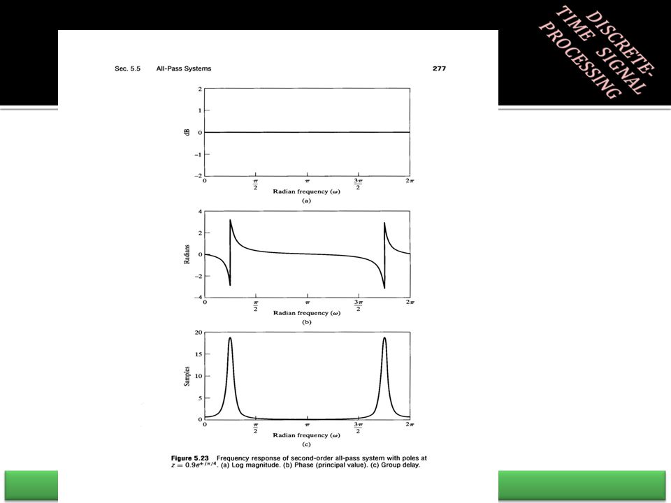
5.5ALL-PASS Systems A system with constant frequency response magnitude Important uses such as compensating for phase distortion Simple all-pass system Most general form with real impulse response A: positive constant, d k : real poles, c k : complex poles Chapter 5: Transform Analysis of LTI Systems40

42
Phase of All-Pass Systems Let’s write the phase with a represented in polar form The group delay of this system can be written as For stable and causal system |r|<1 –Group delay of all-pass systems is always positive Phase between 0 and is always negative Chapter 5: Transform Analysis of LTI Systems41

47
5.6Minimum-Phase Systems A system with all poles and zeros inside the unit circle. Both the system function and the inverse is causal and stable. Name “minimum-phase” comes from the property of the phase Given a magnitude-squared system function that is minimum phase –The original system is uniquely determined Minimum-phase and All-pass decomposition –Any rational system function can be decomposed as Chapter 5: Transform Analysis of LTI Systems46

48
Example 1: Minimum-Phase System Consider the following system One pole inside the unit circle: –Make part of minimum-phase system One zero outside the unit circle: –Add an all-pass system to reflect this zero inside the unit circle Chapter 5: Transform Analysis of LTI Systems47

49
Example 2: Minimum-Phase System Consider the following system One pole inside the unit circle, and complex conjugate zero pair outside the unit circle Chapter 5: Transform Analysis of LTI Systems48

50
Example 2 Cont’d Chapter 5: Transform Analysis of LTI Systems49

51
Frequency-Response Compensation In some applications a signal is distorted by an LTI system. Could filter with inverse filter to recover input signal. –Would work only with minimum-phase systems Make use of minimum-phase all-pass decomposition. –Invert minimum phase part Assume a distorting system H d (z) and Decompose it into Define compensating system as Cascade of the distorting system and compensating system Chapter 5: Transform Analysis of LTI Systems50
 and Decompose it into Define compensating system as Cascade of the distorting system and compensating system Chapter 5: Transform Analysis of LTI Systems50.")
52
مثال :

57
پاسخ فرکانسي سيستم

58
در حالت حداقل فاز

59
Properties of Minimum-Phase Systems Minimum Phase-Lag Property: –Continuous phase of a non-minimum-phase system –All-pass systems have negative phase between 0 and . –So any non-minimum phase system will have a more negative phase compared to the minimum-phase system. –The negative of the phase is called the phase-lag function. –The name minimum-phase comes from minimum phase- lag. Chapter 5: Transform Analysis of LTI Systems58

60
Properties of Minimum-Phase Systems Minimum Group-Delay Property: –Group-delay of all-pass systems is positive. –Any non-minimum-phase system will always have greater group delay. Chapter 5: Transform Analysis of LTI Systems59

61
Properties of Minimum-Phase Systems Minimum Energy-Delay Property –Minimum-phase system concentrates energy in the early part. Proof: –Consider a minimum-phase system H min (z). –Any H(z) that has the same magnitude response as H min (z) has the same poles as H min (z) any number of zeros of H min (z) are flipped outside the unit-circle –Decompose one of the zeros of H min (z) –Write H(z) that has the same magnitude response as H min (z) –We can write these in time domain Chapter 5: Transform Analysis of LTI Systems60
. –Any H(z) that has the same magnitude response as H min (z) has the same poles as H min (z) any number of zeros of H min (z) are flipped outside the unit-circle –Decompose one of the zeros of H min (z) –Write H(z) that has the same magnitude response as H min (z) –We can write these in time domain Chapter 5: Transform Analysis of LTI Systems60.")
62
Derivation Cont’d Evaluate each sum And the difference is Since |z k |<1 Chapter 5: Transform Analysis of LTI Systems61

66
5.7Linear Phase Systems Ideal Delay System Magnitude, phase, and group delay Impulse response (by direct calculation of Inverse Fourier Transform) If =n d is an integer For integer linear phase system delays the input Chapter 5: Transform Analysis of LTI Systems65
 If =n d is an integer For integer linear phase system delays the input Chapter 5: Transform Analysis of LTI Systems65")
67
Linear Phase Systems For non-integer the output is an interpolation of samples Easiest way of representing is to think of it in continuous This representation can be used even if x[n] was not originally derived from a continuous-time signal The output of the system is Samples of a time-shifted, band-limited interpolation of the input sequence x[n] A linear phase system can be thought as A zero-phase system output is delayed by Chapter 5: Transform Analysis of LTI Systems66
![Linear Phase Systems For non-integer the output is an interpolation of samples Easiest way of representing is to think of it in continuous This representation can be used even if x[n] was not originally derived from a continuous-time signal The output of the system is Samples of a time-shifted, band-limited interpolation of the input sequence x[n] A linear phase system can be thought as A zero-phase system output is delayed by Chapter 5: Transform Analysis of LTI Systems66](http://images.slideplayer.com/16/4878302/slides/slide_67.jpg "Linear Phase Systems For non-integer the output is an interpolation of samples Easiest way of representing is to think of it in continuous This representation can be used even if x[n] was not originally derived from a continuous-time signal The output of the system is Samples of a time-shifted, band-limited interpolation of the input sequence x[n] A linear phase system can be thought as A zero-phase system output is delayed by Chapter 5: Transform Analysis of LTI Systems66")
68
Symmetry of Linear Phase Impulse Responses Linear-phase systems Suppose for example: The corresponding impulse response is: Chapter 5: Transform Analysis of LTI Systems67

69
If is an integer, Impulse response is symmetric about Symmetry of Linear Phase Impulse Responses

70
Chapter 5: Transform Analysis of LTI Systems69 =5 =4.5 =4.3

71
If 2α is an integer, the corresponding impulse response has even symmetry about α. i.e., This is a sufficient but not necessary condition for the system to have a linear phase. Symmetry of Linear Phase Impulse Responses

72
Generalized Linear Phase System Generalized Linear Phase Additive constant in addition to linear term Has constant group delay And linear phase of general form Chapter 5: Transform Analysis of LTI Systems71

73
Condition for Generalized Linear Phase We can write a generalized linear phase system response as or equivalently as The tangent of the phase angle of this system is Chapter 5: Transform Analysis of LTI Systems72

74
Condition for Generalized Linear Phase Cross multiply to get necessary condition for generalized linear phase Chapter 5: Transform Analysis of LTI Systems73

75
Symmetry of Generalized Linear Phase Necessary but not sufficient condition for being generalized linear phase It is not sufficient, however, and, due to its implicit nature, it does not tell us how to find a linear-phase system. Chapter 5: Transform Analysis of LTI Systems74

76
Symmetry of Generalized Linear Phase For =0 or : For = /2 or 3 /2 It can be shown that one set of conditions that satisfy this necessary equation (*) are: – =0 or ,, and Also another set of conditions are: - = /2 or 3 /2,, and Chapter 5: Transform Analysis of LTI Systems75
 are: – =0 or ,, and Also another set of conditions are: - = /2 or 3 /2,, and Chapter 5: Transform Analysis of LTI Systems75")
77
Causal Generalized Linear-Phase System If the system is causal and generalized linear-phase Since h[n]=0 for n<0 we get An FIR impulse response of length M+1 is generalized linear phase if they are symmetric Here M is an even integer Chapter 5: Transform Analysis of LTI Systems76
![Causal Generalized Linear-Phase System If the system is causal and generalized linear-phase Since h[n]=0 for n<0 we get An FIR impulse response of length M+1 is generalized linear phase if they are symmetric Here M is an even integer Chapter 5: Transform Analysis of LTI Systems76](http://images.slideplayer.com/16/4878302/slides/slide_77.jpg "Causal Generalized Linear-Phase System If the system is causal and generalized linear-phase Since h[n]=0 for n<0 we get An FIR impulse response of length M+1 is generalized linear phase if they are symmetric Here M is an even integer Chapter 5: Transform Analysis of LTI Systems76")
78
It can be shown that if: –Where is a real, even, periodic function of ω Similarly, if: –Where is a real, odd, periodic function of ω

79
Type I FIR Linear-Phase System Type I system is defined with symmetric impulse response –M is an even integer The frequency response can be written as Where Chapter 5: Transform Analysis of LTI Systems78

80
Type II FIR Linear-Phase System Type II system is defined with symmetric impulse response –M is an odd integer The frequency response can be written as Chapter 5: Transform Analysis of LTI Systems79

81
Type III FIR Linear-Phase System Type III system is defined with antisymmetric impulse response –M is an even integer The frequency response can be written as Chapter 5: Transform Analysis of LTI Systems80

82
Type IV FIR Linear-Phase System Type IV system is defined with antisymmetric impulse response –M is an odd integer The frequency response can be written as Chapter 5: Transform Analysis of LTI Systems81

83
Location of Zeros for Symmetric Cases For type I and II we have So if z 0 is a zero 1/z 0 is also a zero of the system If h[n] is real and z 0 is a zero z 0 * is also a zero So for real and symmetric h[n] zeros come in sets of four Special cases where zeros come in pairs –If a zero is on the unit circle reciprocal it is equal to its conjugate –If a zero is real its conjugate is equal to itself Chapter 5: Transform Analysis of LTI Systems82
![Location of Zeros for Symmetric Cases For type I and II we have So if z 0 is a zero 1/z 0 is also a zero of the system If h[n] is real and z 0 is a zero z 0 * is also a zero So for real and symmetric h[n] zeros come in sets of four Special cases where zeros come in pairs –If a zero is on the unit circle reciprocal it is equal to its conjugate –If a zero is real its conjugate is equal to itself Chapter 5: Transform Analysis of LTI Systems82](http://images.slideplayer.com/16/4878302/slides/slide_83.jpg "Location of Zeros for Symmetric Cases For type I and II we have So if z 0 is a zero 1/z 0 is also a zero of the system If h[n] is real and z 0 is a zero z 0 * is also a zero So for real and symmetric h[n] zeros come in sets of four Special cases where zeros come in pairs –If a zero is on the unit circle reciprocal it is equal to its conjugate –If a zero is real its conjugate is equal to itself Chapter 5: Transform Analysis of LTI Systems82")
84
Location of Zeros for Symmetric Cases Special cases where a zero come by itself –If z= 1 both the reciprocal and conjugate is itself Particular importance of z=-1 –If M is odd implies that –Cannot design high-pass filter with symmetric FIR filter and M odd Chapter 5: Transform Analysis of LTI Systems83

85
Location of Zeros for Antisymmetric Cases For type III and IV we have All properties of symmetric systems holds Particular importance of both z=+1 and z=-1 –If z=1 Independent from M: odd or even –If z=-1 If M+1 is odd implies that Chapter 5: Transform Analysis of LTI Systems84

86
Typical Zero Locations a) type I, b) type II, c) type III, d) type IV Chapter 5: Transform Analysis of LTI Systems85
 type I, b) type II, c) type III, d) type IV Chapter 5: Transform Analysis of LTI Systems85")
87
Relation of FIR Linear Phase to Minimum-Phase In general a linear-phase FIR system is not minimum-phase We can always write a linear-phase FIR system as Where And M i is the number of zeros H min (z) covers all zeros inside the unit circle H uc (z) covers all zeros on the unit circle H max (z) covers all zeros outside the unit circle Chapter 5: Transform Analysis of LTI Systems86
 covers all zeros inside the unit circle H uc (z) covers all zeros on the unit circle H max (z) covers all zeros outside the unit circle Chapter 5: Transform Analysis of LTI Systems86")
Similar presentations


![Z-Transform Fourier Transform z-transform. Z-transform operator: The z-transform operator is seen to transform the sequence x[n] into the function X{z},](/17/5301252/big_thumb.jpg "Z-Transform Fourier Transform z-transform. Z-transform operator: The z-transform operator is seen to transform the sequence x[n] into the function X{z},>")


>")


 Kevin D. Donohue Electrical and Computer Engineering University of Kentucky.>")


