Download presentation
Presentation is loading. Please wait.

1
Class Day Fourteen Class Day Fourteen

2
Chapter 10 Masonry Load bearing Wall Construction

3
LOAD BEARING MASONRY WALLS are walls designed to be part of the structural system of a building. walls designed to be part of the structural system of a building. A load bearing wall will carry a portion of the weight of a roof, or in the case of two or more stories, a portion of the weight of the floors. A wall is subject to failure for several reasons, which may be due to: vertical weight imposed; crushing, buckling horizontal forces, such as wind. horizontal forces due to seismic loads. Structurally, all potential conditions must be considered – then the wall is assembled according to safe design standards.

4
Early buildings made with masonry load bearing walls created problems in settlement of the foundation, when connected to masonry walls that were not load bearing. Because of uneven loading, the load bearing walls settled into the ground, but the non bearing (end) walls did not, resulting in cracking of the masonry at corners. Corners were reinforced with brick or stone called “Quoins” loading, the load bearing walls settled into the ground, but the non bearing (end) walls did not, resulting in cracking of the masonry at corners. Corners were reinforced with brick or stone called “Quoins”
 walls did not, resulting in cracking of the masonry at corners. Corners were reinforced with brick or stone called Quoins loading, the load bearing walls settled into the ground, but the non bearing (end) walls did not, resulting in cracking of the masonry at corners. Corners were reinforced with brick or stone called Quoins .")
5
The photo shows quoins installed at the corners of this building. Quoins quickly became a decorative feature, but originally were installed to be a structural item, usually made of brick or stone.

6
There are two types of masonry walls: Reinforced and Non-Reinforced Because masonry is a brittle material with virtually no allowance for tensile stress, all masonry construction must be reinforced to compensate for tension due to uneven settlement, shrinkage due to loss of moisture, and movement due to plastic soils. But not necessarily for structural properties due to imposed loading. Because masonry is a brittle material with virtually no allowance for tensile stress, all masonry construction must be reinforced to compensate for tension due to uneven settlement, shrinkage due to loss of moisture, and movement due to plastic soils. But not necessarily for structural properties due to imposed loading. This type of reinforcing is installed within the mortar bed in horizontal joints. Reinforcing is made of steel wire, meshed to a pattern to resist lateral forces, and electrically welded.

7
NON REINFORCED Construction that does not require the integrity of structural loading beyond the requirements of a free standing wall, such as small single story buildings with light loads. These are built by standard procedures, including mortar fill and wall reinforcing that is necessary only for resistance to cracking due to shrinkage or expansion due to temperature difference – not for structural loading.

8
–These would also include low rise units which may have cores filled with concrete for use as stem walls as parts of foundations, generally too short to have a tendency to bend. –The model building codes require analysis on all structural members, to protect the public against assembly of parts that have not been qualified as safe.

9
–And, forces can occur that may be somewhat indeterminate in structural analysis – due to unexpected loads such as wind gusts, soil movement, and unforseen forces. For those reasons, the Building Department of the City of Lubbock, as do other responsible entities, limit the construction height of non reinforced masonry walls to no higher than 18 times their thickness. So, non- reinforced wall limits include: A wall made of 8” CMU has a maximum height of 12’-0”. Likewise, a 12” wall cannot be higher than 18’-0”.

10
REINFORCED MASONRY WALLS are units that –Are designed with the necessary structural components to resist loading that induce tension, compressive, and shearing forces. Such reinforcement generally is done with steel rods imbedded in concrete within the masonry. –Since a long, high wall is a relative thin membrane of a building envelope, the tendency to fail under loading is by buckling, which may be a combination of twisting and bending. –Shorter units are more stiff, and tendency to fail under loading is by crushing and shear.

11
–Structural components must be added to the assembly of such members that will resist all tendencies to fail because of loads. –Generally, the combination of masonry, mortar, and concrete fill is sufficient to resist crushing, or compressive forces in small buildings. –Reinforcing steel is installed through masonry cells, which are then filled with concrete to become a resisting tensile material held in place by the concrete, to tie the individual masonry units together into a structural mass.

12
The tendency for a member to bend because of building loads, induces all three types of stress; compressive, tensile, and shearing forces. Masonry may be able to resist compression and shear if the stress is within its allowable limits, but reinforcing steel is required to resists tension forces. Since brittle materials rupture at an angle relative to their face direction, reinforcing steel, if required, resists shear through a concept called “diagonal tension.”

13
Reinforced Masonry Walls

14
Cell Reinforcing – vertical steel Bars installed @ 2’-0” oc, then Cells filled with concrete. A SINGLE LAYER OF MASONRY WALL IS CALLED A ‘WYTHE’

15
STRUCTURE IN BUILDING MATERIALS All materials used in construction have weight, which may have to be supported by some other material. All construction materials have a quality about them that can resist the forces imposed by weights of other materials. A FORCE is an amount of load caused by weights of building materials, and anticipated loads caused by snow, water, building contents, people, etc. Forces are loads due to these weights caused by GRAVITY.

16
All forces of gravity are vertically downward, UNLESS redirected by the resistance of some member, in which case it may become horizontal, vertical, or a combination. Wind and seismic loads are horizontal forces, but may change direction because of redirection. STRESS is a force over a unit of area. Stress may have units such as pounds per square inch, or pounds per square foot, or in the case of metric units, grams per square centimeter. If a person stands on two feet, and weighs 180 pounds, and the area of each shoe sole is 40 sq.in., then a stress on the floor of 180 / 80 equals 2.25 pounds per square inch. But, If the person stands on one foot, the stress on the floor 4.5 pounds per square inch – twice as much.

17
All construction materials that are placed for the purpose of resisting forces, have a tested ALLOWABLE STRESS. Or an amount of FORCE they can resist over a unit of its area. FOR INSTANCE, some common building material: material allowable stress in pounds per square Concrete3,000 Brick 500 CMU 800 Wood 900 Steel 24,000

18
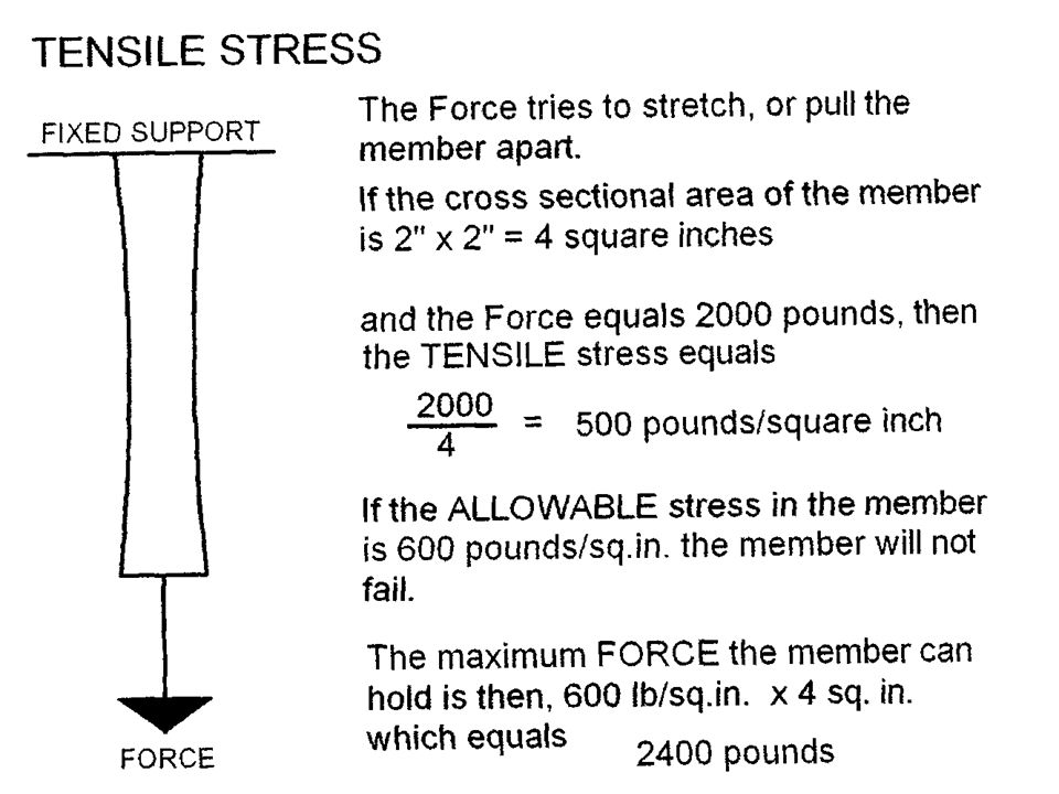
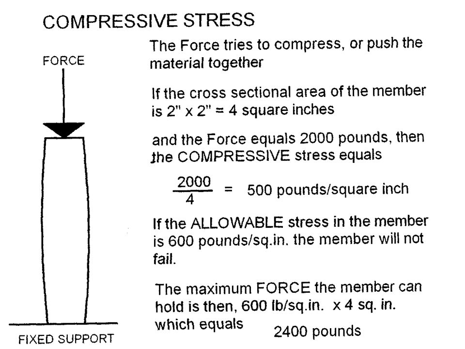
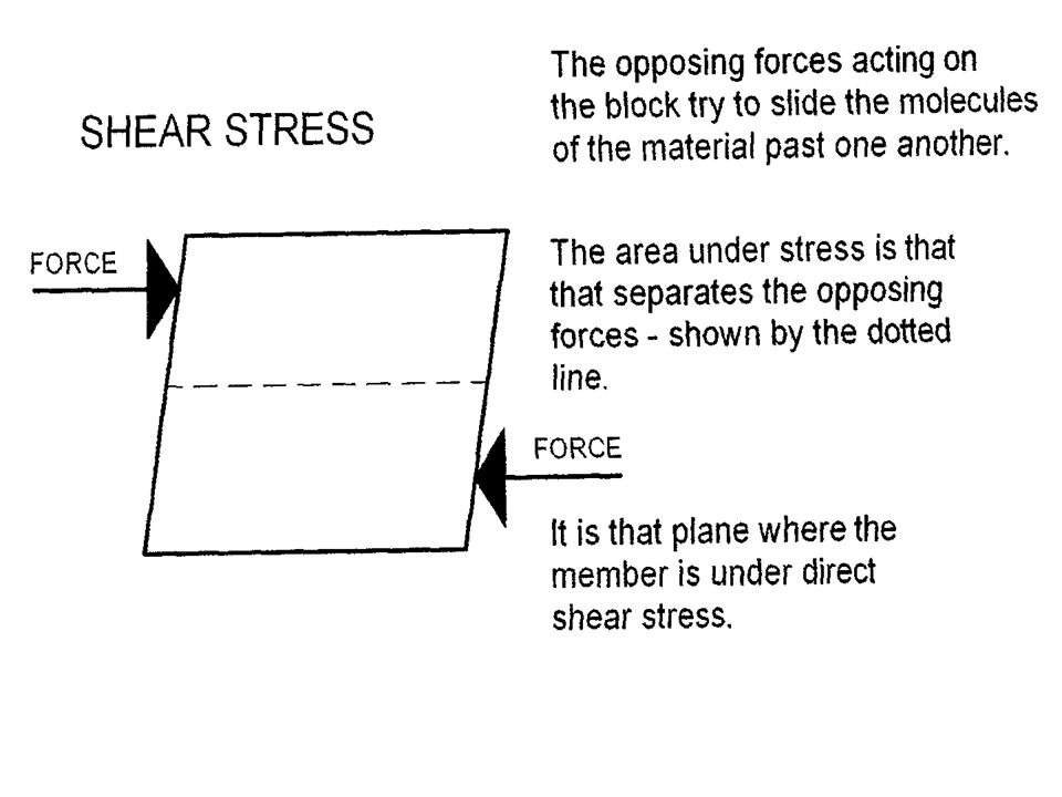
The preceding allowable figures do not indicate WHAT KIND OF STRESS they resist, and there are three types: TENSILE STRESS: The type that tends to stretch a material, as though the forces were attempting to pull the molecules of the material apart. COMPRESSIVE STRESS: The type that tends to compress, or press together, or crush the molecules of the material. SHEAR STRESS: The type that tends to slide or twist the molecules of the material apart. The numerical value of stress equals the amount of force divided by the cross section area of the member that is subject to force.

22
As a result, a mathematical formula can be realized; Stress equals force divided by the area affected. or,S = F / A whereS = stress in pounds per square inch F = total pounds A = area in square inches

23
Another type of stress is created by bending, which is a combination of the first three, and it is through that investigation that beam requirements are analyzed and selected. Imagine a load bearing wall made of concrete masonry units. An opening in the wall is necessary to have access to the inside. Since the wall supports a portion of the roof load at the eave and the weight of the CMU above the opening, a beam must be installed to compensate for the void of the opening.

24
Elevation of concrete block wall with opening

25
The beam can be isolated and examined, in order to determine what tendencies exist due to the weight it must support over the opening. All building materials are said to be elastic. In other words they deform when subjected to loading. If the deformations are not excessive, the members remain viable as structural components. Materials under tension tend to stretch Materials under compression tend to shrink Materials under shear tend to deform or twist When a horizontal beam supported only at the ends is loaded with a downward force, it has a TENDENCY to bend downward.

26
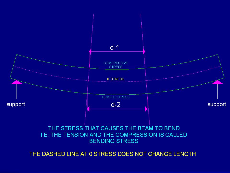
As a member bends, certain things must be realized; First there must be no failures due to any kind of stress, so the square ends of the beam remain square. Second, if the beam is loaded consistently, the deformation, or bend will be downward and will assume the shape of a portion of the circumference of a circle. And as the beam bends, the length of the top of the beam will become shorter, and the length of the bottom of the beam will become longer.

28
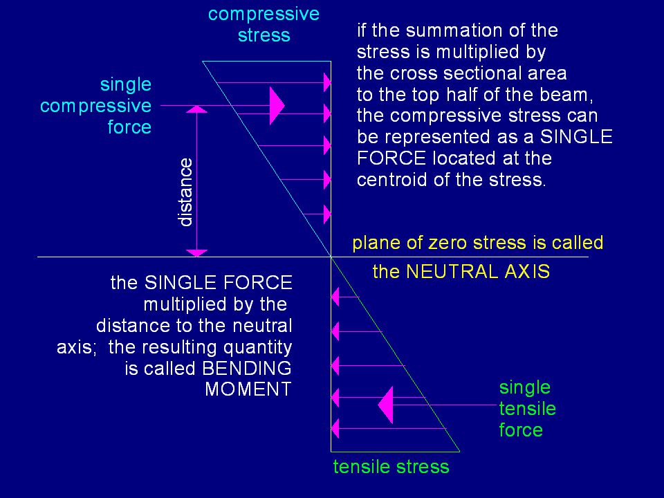
It must follow that, if compressive stress is maximum at the top of the beam and tensile stress is maximum at the bottom of the beam, there is a plane where no stress occurs – since compression is the opposite of tension. Realize that the definition of stress is an amount of force divided by the area in which the force acts. Likewise, properly located, a single force can represent the sum of the stress multiplied by area.

30
TO SUMMARIZE: WHEN STRUCTURAL MEMBERS ARE SUBJECTED TO IMPOSED LOADS, FORCES ARE CREATED, WHICH IN TURN CAN CAUSE DIRECT TO SUMMARIZE: WHEN STRUCTURAL MEMBERS ARE SUBJECTED TO IMPOSED LOADS, FORCES ARE CREATED, WHICH IN TURN CAN CAUSE DIRECT Tensile stress Compressive stress Shear stress but not necessarily all at the same time. but not necessarily all at the same time. AND WHEN BENDING OF A MEMBER OCCURS, –Bending stress happens, which simultaneously causes TensionCompressionShear

31
AND NOW EVERYONE TAKE OUT A SHEET OFBLANK PAPER AND DO THIS EXERCISE. THIS CONSTITUTES QUIZ NUMBER THREE

32
ONE A solid wood block 2’ x 2’ x 2’ is used to support the weight of a car axle which presses down on the ground a total of 1500 pounds. Find the amount of stress the block makes on the ground – in units of pounds per square foot. TWO A square steel strap ½” x 4” in cross section can have a maximum stress of 18,000 pounds per square inch in tension. Find the maximum tensile load it can safely hold. As soon as you finish, place your name on the paper, then drop it in the chair at the back and you are free to go.

Similar presentations