Download presentation
Presentation is loading. Please wait.

1
1

2
By Dr. Attaullah Shah Swedish College of Engineering and Technology Wah Cantt. Reinforced Concrete Design-II Lec-3 Retaining walls

3
Purposes of Retaining walls −Retaining walls are structures designed to restrain soil to unnatural slopes. −They are used to bound soils between two different elevations often in areas of terrain possessing undesirable slopes or in areas where the landscape needs to be shaped severely and engineered for more specific purposes like hillside farming or roadway overpasses.

4
Types of Retaining walls Gravity walls depend on their mass (stone, concrete or other heavy material) to resist pressure from behind and may have a 'batter' setback to improve stability by leaning back toward the retained soil. For short landscaping walls, they are often made from mortarless stone or segmental concrete units (masonry units).
..")
5
−Cantilevered retaining wall: −Cantilevered retaining walls are made from an internal stem of steel-reinforced, cast-in-place concrete or mortared masonry (often in the shape of an inverted T). −These walls cantilever loads (like a beam) to a large, structural footing, converting horizontal pressures from behind the wall to vertical pressures on the ground below. − Sometimes cantilevered walls are buttressed on the front, or include a counter fort on the back, to improve their strength resisting high loads. Buttresses are short wing walls at right angles to the main trend of the wall. These walls require rigid concrete footings below seasonal frost depth. This type of wall uses much less material than a traditional gravity wall.
 to a large, structural footing, converting horizontal pressures from behind the wall to vertical pressures on the ground below. − Sometimes cantilevered walls are buttressed on the front, or include a counter fort on the back, to improve their strength resisting high loads. Buttresses are short wing walls at right angles to the main trend of the wall. These walls require rigid concrete footings below seasonal frost depth. This type of wall uses much less material than a traditional gravity wall..")
6
Drainage of Retaining walls

7
Sheet piling −Sheet pile retaining walls are usually used in soft soils and tight spaces. Sheet pile walls are made out of steel, vinyl or wood planks which are driven into the ground. −For a quick estimate the material is usually driven 1/3 above ground, 2/3 below ground, but this may be altered depending on the environment. −Taller sheet pile walls will need a tie-back anchor, or "dead-man" placed in the soil a distance behind the face of the wall, that is tied to the wall, usually by a cable or a rod. Anchors are then placed behind the potential failure plane in the soil.

8
Failure of Retaining walls −Failure of retaining walls is more frequent as compared to other RC structures due to −Poor design assumptions −Changing and unpredictable subsoil and backfilled conditions −Poor masonry work/material strength and improper bonding −Lack of drainage facilities and provisions −Can you think of some more reasons?

9
Lateral pressure on Retaining walls −Active lateral pressure ( Can you define) −Passive lateral pressure − The general equation ( Rankine Eq) for the active and passive coeff. for a surcharge angle of ϐ and internal angle of friction Φ is given as: − For horizontal backfill, the expression is given as −The total lateral active and passive pressure are given as:

10
Earth pressure for various conditions

11
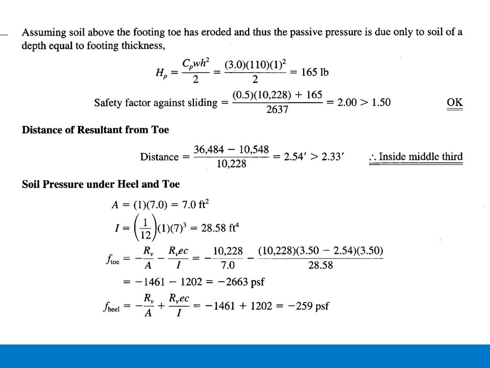
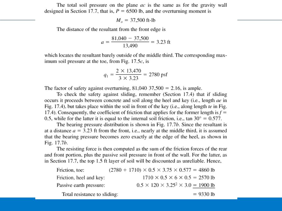
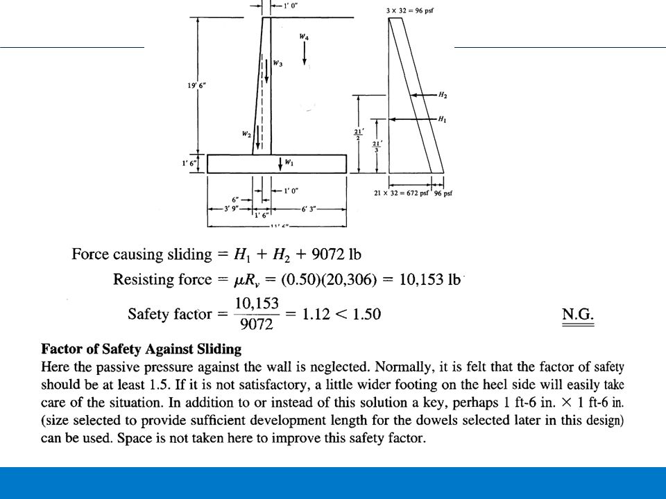
Modes of failure of retaining walls −The individual components of the wall may fail −The wall as a whole may be displaced due to sliding −The wall may get overturned −The factor of safety against the sliding must be at least 1.5 −The horizontal force acting on the retaining wall is Ph which is resisted by the vertical component of lateral pressure and resisting weight of the load on the toe: − To have min factor of safety of 1.5 −If the required sliding resistance is not provided by the weight, then key may be provided beneath the stem −The pressure under the footing must not exceed the allowable bearing capacity of soil

13
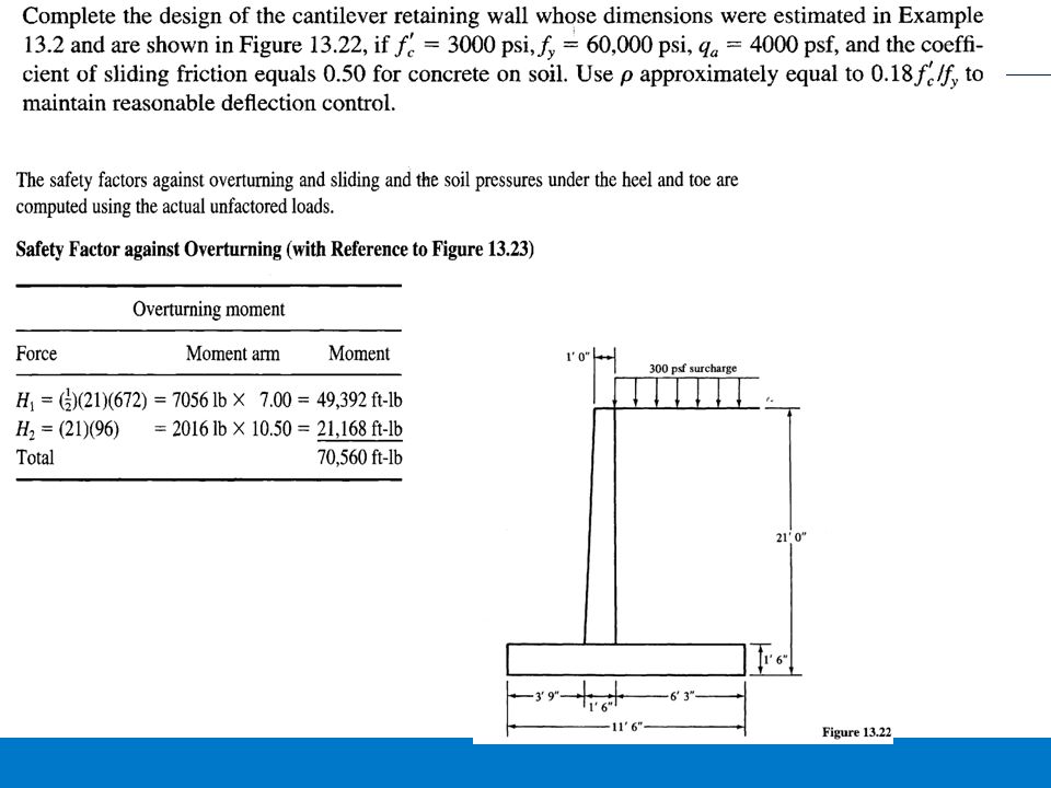
Overturning of Retaining Wall:

15
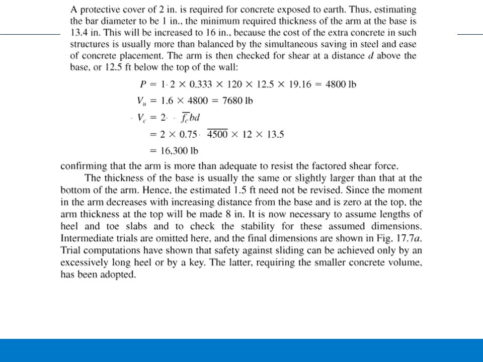
The top width of the stem=0.08h = 0.08*15 = 1.20ft= 14.4 in Assumed 18in Depth of the base= 0.12h to 0.16h=14.4in to 28in Assume 24in Width of the base= 0.5h to 1.25 h = 7.5 ft to 11.5 ft Assume 10ft Width of heel= 0.5d to d = 12 to 24 in Assumed 9in

18
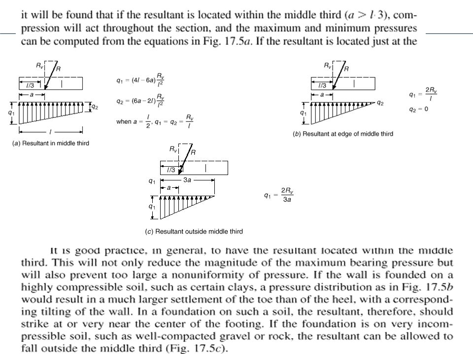
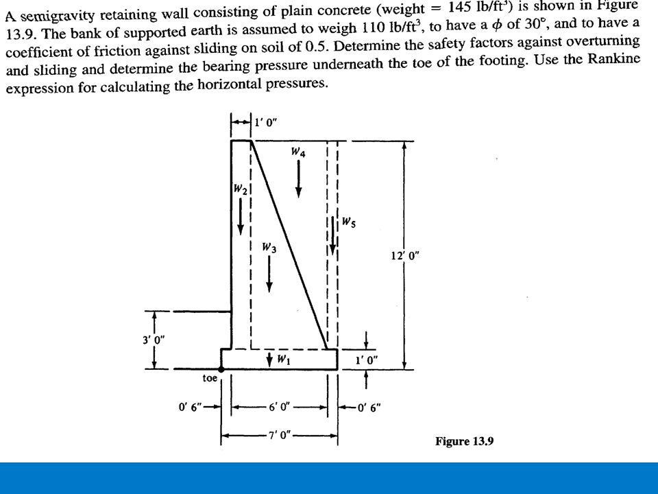
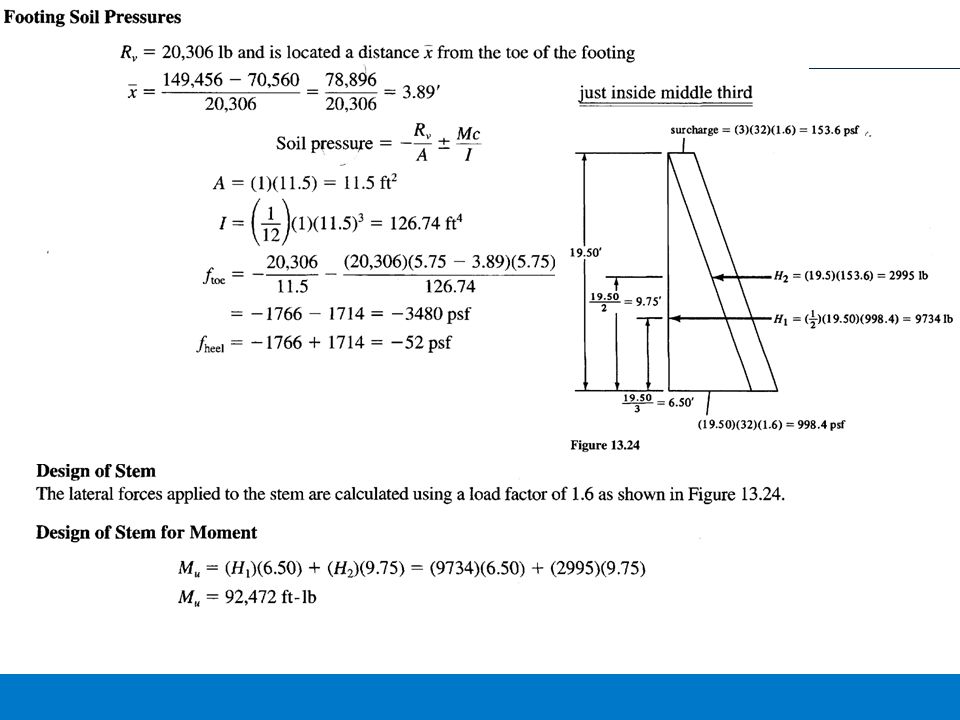
Design of semi gravity retaining walls −The retaining walls which resist the lateral pressure by means of its weight and developed soils. −The wall thickness is selected such that no part of the wall is in tension −The resultant force must pass through the middle third to fulfill this condition.

22
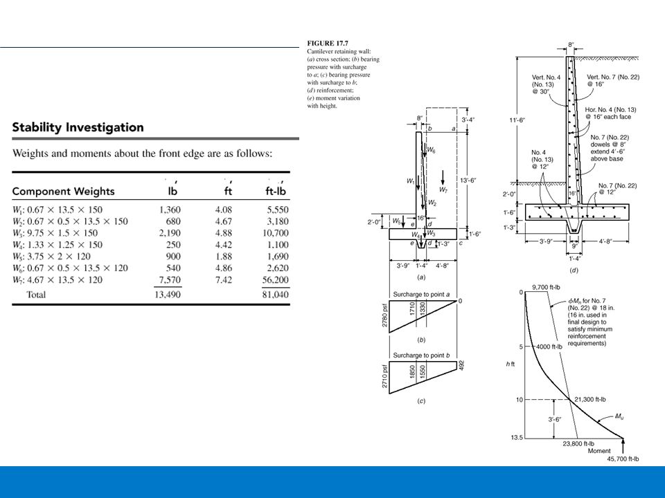
Effect of Surcharge −If the surcharge is above the backfill it will induce a uniform lateral pressure on the retaining wall in addition to the back fill pressure. −In case the surcharge is away from the face of wall. The lateral pressure effect of the surcharge will be effective at 45 degree from the surcharge as shown in the figure ( Partial pressure due to partial surcharge)
.")
23
Estimating the sizes of Cantilever retaining walls −Highest of the wall: −Depends on the height of the back fill. −The foundation of retaining wall is usually 3-6 feet below the ground level depending the soil condition and weather effects. In colder regions, the depth has to be sufficiently below the ground level to avoid the damage due to frost action − The various min dimensions are shown in the Figure. −The reinforcement is main or stem reinforcement and temperature reinforcement along the face of retaining wall.

45
Assigments

Similar presentations