Download presentation
Presentation is loading. Please wait.

1
Lakshmi N. Sankar lsankar@ae.gatech.edu
Wind Engineering Module 5.1: Wind Turbine Design Overview, Radius, and Airfoils Lakshmi N. Sankar

2
Recap In Module 1, we looked at an overview of the course objectives, syllabus, and deliverables. We also reviewed history of wind technology, nomenclature, and case studies. In Module 2, we looked at the wind turbine as an actuator disk, and established the theoretical maximum for power that may be captured. In module 3, we reviewed airfoil aerodynamics, and discussed how to compute lift and drag coefficients. We also reviewed airfoil design issues. In Module 4, we looked at how wind turbines may be modeled using blade element theory. We also looked at some commonly available public domain performance codes.

3
Overview In this module, we will look at how to design wind turbines.
This study is purely from an aerodynamic perspective. In practice, wind turbine design is a multidisciplinary optimization problem. Unlike wind turbine analysis, there are no unique solutions to a design problem. This is why wind turbines from various manufacturers look different.

4
Wind Turbine Design is an Interdisciplinary Problem
Structures, Structural Dynamics, Vibrations, Stability, Fatigue Life Transmission, gears, tower, power systems, etc. Aerodynamics Noise, aesthetics Control systems for RPM, Pitch, Yaw Cost

5
Parameters to be Chosen
We need to decide on Number of blades Blade planform (i.e. how does chord vary with radius)? Blade radius Blade twist distribution Airfoils RPM Decisions about variable RPM, variable pitch We need to consider cost, noise, vibrations, fatigue, etc as well.
 Blade radius. Blade twist distribution. Airfoils. RPM. Decisions about variable RPM, variable pitch. We need to consider cost, noise, vibrations, fatigue, etc as well.")
6
Starting Point Before starting a design, it is a good idea to survey existing concepts and collect data. Learn from other designers’ experience and success, and mistakes. While much of the information for commercial systems is proprietary, there are good public resources.

7
Some References cited in NREL/TP-500-40566
[1] Harrison, R.; Jenkins, G.; Cost Modeling of Horizontal Axis Wind Turbines. ETSU W/34/00170/REP. University of Sunderland, School of Environment, December 1993 [2] Griffin, D. A. WindPACT Turbine Design Scaling Studies Technical Area 1 -- Composite Blades for 80- to 120-Meter Rotor; 21 March March NREL/SR Golden, CO: National Renewable Energy Laboratory, April 2001. [3] Smith, K. WindPACT Turbine Design Scaling Studies Technical Area 2: Turbine, Rotor and Blade Logistics; 27 March December NREL/SR Work performed by Global Energy Concepts, LLC, Kirkland, WA. Golden, CO: National Renewable Energy Laboratory, June 2001.

8
References (Continued)
[4] WindPACT Turbine Design Scaling Studies Technical Area 3 -- Self-Erecting Tower and Nacelle Feasibility: March March (2001). NREL/SR Work performed by Global Energy Concepts, LLC, Kirkland, WA. Golden, CO: National Renewable Energy Laboratory, May 2001. [5] Shafer, D. A.; Strawmyer, K. R.; Conley, R. M.; Guidinger, J. H.; Wilkie, D. C.; Zellman, T. F.; Bernadett, D. W. WindPACT Turbine Design Scaling Studies: Technical Area 4 -- Balance-of-Station Cost; 21 March March NREL/SR Work performed by Commonwealth Associates, Inc., Jackson, MI. Golden, CO: National Renewable Energy Laboratory, July 2001. [6] Malcolm, D. J.; Hansen, A. C. WindPACT Turbine Rotor Design Study: June June 2002 (Revised). NREL/SR Work performed by Global Energy Concepts, LLC, Kirkland, WA; and Windward Engineering, Salt Lake City, UT. Golden, CO: National Renewable Energy Laboratory, April 2006 (revised).
. NREL/SR Work performed by Global Energy Concepts, LLC, Kirkland, WA. Golden, CO: National Renewable Energy Laboratory, May [5] Shafer, D. A.; Strawmyer, K. R.; Conley, R. M.; Guidinger, J. H.; Wilkie, D. C.; Zellman, T. F.; Bernadett, D. W. WindPACT Turbine Design Scaling Studies: Technical Area 4 -- Balance-of-Station Cost; 21 March March NREL/SR Work performed by Commonwealth Associates, Inc., Jackson, MI. Golden, CO: National Renewable Energy Laboratory, July [6] Malcolm, D. J.; Hansen, A. C. WindPACT Turbine Rotor Design Study: June June 2002 (Revised). NREL/SR Work performed by Global Energy Concepts, LLC, Kirkland, WA; and Windward Engineering, Salt Lake City, UT. Golden, CO: National Renewable Energy Laboratory, April 2006 (revised).")
9
References (Continued)
[7] Poore, R.; Lettenmaier, T. Alternative Design Study Report: WindPACT Advanced Wind Turbine Drive Train Designs Study; November 1, February 28, NREL/SR Work performed by Global Energy Concepts, LLC, Kirkland, WA. Golden, CO: National Renewable Energy Laboratory, August 2003. [8] Bywaters, G.; John, V.; Lynch, J.; Mattila, P.; Norton, G.; Stowell, J.; Salata, M.; Labath, O.; Chertok, A.; Hablanian, D. Northern Power Systems WindPACT Drive Train Alternative Design Study Report; Period of Performance: April 12, 2001 to January 31, NREL/SR

10
Design Approaches A parametric sweep may be done using a fast but reliable software such as WT_PERF or PROPID to identify best configurations and parametric combinations. One can pose the problem as an optimization problem: maximize power (MW) or MW-Hr for a range of wind conditions, subject to constraints such as cost, weight, fatigue life, etc. PropID has an inverse mode that accomplishes this. One can use genetic algorithms to combine the best features of known configurations (gene pool). PropGA developed by Philippe Giguère
 or MW-Hr for a range of wind conditions, subject to constraints such as cost, weight, fatigue life, etc. PropID has an inverse mode that accomplishes this. One can use genetic algorithms to combine the best features of known configurations (gene pool). PropGA developed by Philippe Giguère.")
11
Which parameters to change?
Rotor radius affects peak power. Recall actuator disk theory says that the power is proportional to disk area. Changing the twist changes the angle of attack and affects lift and drag coefficient. Changing the chord affects the axial induction factor, and to a small extent the tangential induction factor. The goal is to make axial induction factor approach the Betz limit. Caution: The rotor performance is affected by the interplay between these variables.

12
Effect of rotor Radius on Total mass

13
Effect of Blade radius on Cost including profit, overhead (28%)
")
14
Effect of Blade Radius on Tower Mass Tower Cost = $1.50 per kg

15
Airfoils There are several to choose from. You may design your own as well, using Module 3 material, as you gain experience in this field. Dan Somers’ web site is a valuable resource. Prof. Selig at UIUC has an excellent database as well. has a detailed catalog as well.

16
Wind Turbine Airfoils Design Perspective The environment in which wind turbines operate and their mode of operation not the same as for aircraft Roughness effects resulting from airborne particles are important for wind turbines Larger airfoil thicknesses needed for wind turbines Different environments and modes of operation imply different design requirements The airfoils designed for aircraft not optimum for wind turbines The remaining slides are from a short course on PropID at UIUC Prepared by Jim Tangler:

17
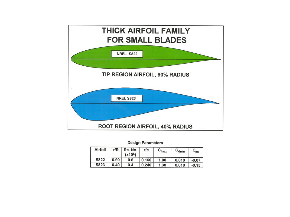
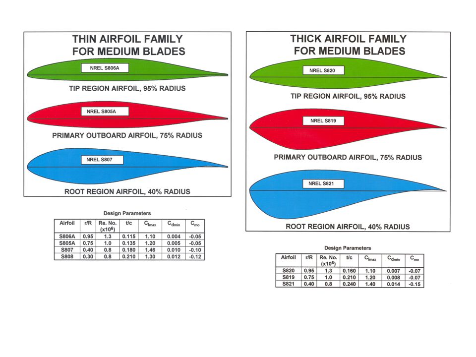
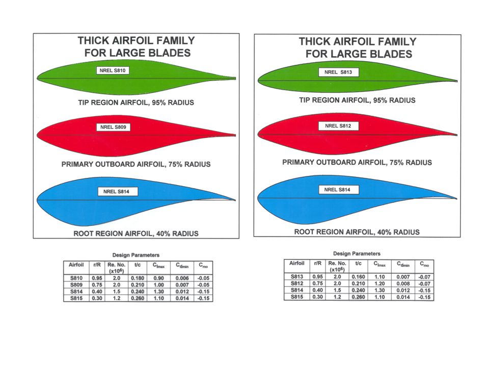
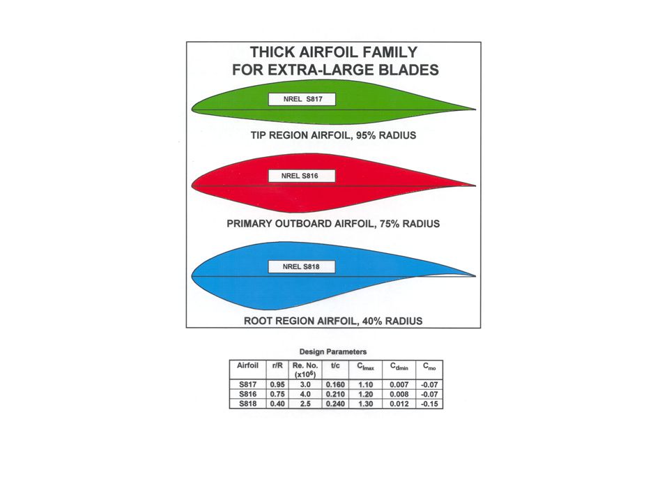
Design Philosophy Design specially-tailored airfoils for wind turbines Design airfoil families with decreasing thickness from root to tip to accommodate both structural and aerodynamic needs Design different families for different wind turbine size and rotor rigidity

18
Main Airfoil Design Parameters
Thickness, t/c Lift range for low drag and Clmax Reynolds number Amount of laminar flow

19
Flexible rotor: 11%–21% t/c Small wind turbines: 10%-16% t/c
Design Criteria for Wind Turbine Airfoils Moderate to high thickness ratio t/c Rigid rotor: 16%–26% t/c Flexible rotor: 11%–21% t/c Small wind turbines: 10%-16% t/c High lift-to-drag ratio Minimal roughness sensitivity Weak laminar separation bubbles

20
Note: Shaded airfoils have been wind tunnel tested.
NREL Advanced Airfoil Families Note: Shaded airfoils have been wind tunnel tested.

25
NREL airfoils vs airfoils designed for aircraft (NACA)
Potential Energy Improvements NREL airfoils vs airfoils designed for aircraft (NACA)
")
26
Other Wind Turbine Airfoils
University of Illinois SG6040/41/42/43 and SG6050/51 airfoil families for small wind turbines (1-10 kW) Numerous low Reynolds number airfoils applicable to small wind turbines Delft (Netherlands) FFA (Sweden) Risø (Denmark)
 Numerous low Reynolds number airfoils applicable to small wind turbines. Delft (Netherlands) FFA (Sweden) Risø (Denmark)")
27
Airfoil Selection Appropriate design Reynolds number Airfoil thickness according to the amount of centrifugal stiffening and desired blade rigidity Roughness insensitivity most important for stall regulated wind turbines Low drag not as important for small wind turbines because of passive over speed control and smaller relative influence of drag on performance High-lift root airfoil to minimize inboard solidity and enhanced starting torque

Similar presentations


 - Rated Power 160 MW – Water Depth 10-15m.>")


>")
 Selection of unique answer B) Brainstorming many ideas.>")


