Download presentation
Presentation is loading. Please wait.

1
Dual Header Pulse Interval Modulation (DH-PIM) Dr. Nawras Aldibbiat Professor Z Ghassemlooy Optical Communications Research Group School of Computing, Engineering & Information Sciences, Northumbria University Email: Nawras.Aldibbiat@unn.ac.uk Tel: 0191 227 3841

2
Outline of the Presentation Introduction DH-PIM principles Power spectral density Artificial light interference Slot & packet error probabilities Optical power & B/W requirements. Multipath propagation Conclusions

3
Introduction DH-PIM was first introduced in 2000: N. M. Aldibbiat & Z. Ghassemlooy: “Dual header-pulse interval modulation (DH ‑ PIM) for optical communication systems”, CSNDSP 2000, Bournemouth, UK, pp. 147- 152, July 2000. Why DH-PIM? Is it ideal for Indoor optical wireless systems?
 for optical communication systems , CSNDSP 2000, Bournemouth, UK, pp , July Why DH-PIM. Is it ideal for Indoor optical wireless systems .")
4
Introduction Line-of-Site Non-Line-of-Site HybridDirected Non-directed

5
Pulse Time Modulation Tree DH-PIM Pulse Time Modulation Analogue Digital Isochronous Anisochronous DPWM MPPM PPM PCM DPIWM DPPM DPIM Anisochronous Isochronous PIWM PIM PFM SWFM PWM PPM

6
Pulse Modulation Symbol Structure

7
DH-PIM symbol structure

8
Symbol Length

9
33.544.555.566.577.58 0 50 100 150 200 250 M [slot] Average symbol length [Ts] PPM DPIM DH-PIM 1 2 Average Symbol Length
![M [slot] Average symbol length [Ts] PPM DPIM DH-PIM 1 2 Average Symbol Length](http://images.slideplayer.com/16/5166834/slides/slide_9.jpg "M [slot] Average symbol length [Ts] PPM DPIM DH-PIM 1 2 Average Symbol Length")
10
Transmission bandwidth DH-PIM requires less bandwidth compared with PPM & DPIM. Bandwidth normalised to OOK: 345678 0 4 8 12 16 20 24 28 32 M [slot] Normalised bandwidth requirements DH-PIM 1 2 3 DPIM PPM

11
Transmission Packet Rate 2345678910 0.5 1 1.5 2 2.5 3 3.5 4 4.5 5 5.5 6 M [bit] Normalised packet transmission rate DH-PIM 3 1 2 DPIM PPM B req = 1 MHz
![Transmission Packet Rate M [bit] Normalised packet transmission rate DH-PIM DPIM PPM B req = 1 MHz](http://images.slideplayer.com/16/5166834/slides/slide_11.jpg "Transmission Packet Rate M [bit] Normalised packet transmission rate DH-PIM DPIM PPM B req = 1 MHz")
12
12345678910 x 10 6 0 100 200 300 400 500 600 700 800 B req [Hz] packet transmission rate [packet/sec] M = 5 PPM DH-PIM 3 2 1 DPIM Transmission Packet Rate - cont.
![x B req [Hz] packet transmission rate [packet/sec] M = 5 PPM DH-PIM DPIM Transmission Packet Rate - cont.](http://images.slideplayer.com/16/5166834/slides/slide_12.jpg "x B req [Hz] packet transmission rate [packet/sec] M = 5 PPM DH-PIM DPIM Transmission Packet Rate - cont.")
13
Transmission Capacity 345678910 0 2 4 6 8 12 M [slot] Normalised transmission capacity DH-PIM 1 2 3 DPIM PPM
![Transmission Capacity M [slot] Normalised transmission capacity DH-PIM DPIM PPM](http://images.slideplayer.com/16/5166834/slides/slide_13.jpg "Transmission Capacity M [slot] Normalised transmission capacity DH-PIM DPIM PPM")
14
DH-PIM system block diagram Transmitter Channel Receiver

15
DH-PIM Transmitter

16
DH-PIM Receiver

17
Simulation Waveforms (16-DH-PIM 1 )
")
18
Simulation Waveforms (16-DH-PIM 1 ) - cont.
 - cont.")
19
Simulation Model

20
Power Spectral Density

21
Power Spectral Density - cont.

22
DH-PIM 1

23
Power Spectral Density - cont. DH-PIM 2

24
2345678 0 1 2 3 4 5 6 7 8 9 10 M [bit] P D C - n o r DH-PIM 1 5 4 3 2 DC component of the PSD
![M [bit] P D C - n o r DH-PIM DC component of the PSD](http://images.slideplayer.com/16/5166834/slides/slide_24.jpg "M [bit] P D C - n o r DH-PIM DC component of the PSD")
25
2345678 0 0.2 0.4 0.6 0.8 1 M [bit] P s l 0 t - n o r DH-PIM 1 3 5 Slot component of the PSD
![M [bit] P s l 0 t - n o r DH-PIM Slot component of the PSD](http://images.slideplayer.com/16/5166834/slides/slide_25.jpg "M [bit] P s l 0 t - n o r DH-PIM Slot component of the PSD")
26
Artificial light interference Artificial light (e.g. Fluorescent) induces periodic interference that contain harmonics at low frequencies This interference can be reduced by employing a high-pass filter, but … this results in baseline wander, which is more severe in modulation schemes that contain high power at DC and low frequencies. Therefore … there is a trade-off between the extent of artificial light interference rejection and the severity of baseline wander
 induces periodic interference that contain harmonics at low frequencies This interference can be reduced by employing a high-pass filter, but … this results in baseline wander, which is more severe in modulation schemes that contain high power at DC and low frequencies. Therefore … there is a trade-off between the extent of artificial light interference rejection and the severity of baseline wander .")
27
Artificial light interference 0123456 0 0.2 0.4 0.6 0.8 1 Normalised frequency (f / R b ) PSD (linear units) M = 4 (L = 16) DH-PIM (alpha=2) DH-PIM (alpha=1) DPPM OOK-NRZ PSD for OOK, DPPM and DH-PIM ( =1 and = 2) for M = 4
 PSD (linear units) M = 4 (L = 16) DH-PIM (alpha=2) DH-PIM (alpha=1) DPPM OOK-NRZ PSD for OOK, DPPM and DH-PIM ( =1 and = 2) for M = 4")
28
Artificial light interference – cont. Simulation block diagram 1 Assumptions: -a rectangular pulse shape -an equal average transmitted optical power for all systems

29
Artificial light interference – cont. - 8-DH-PIM 1 on non-dispersive channel - For f c /R b < 0.01, an additional 5 dB of power is required when R b is increased from 1 Mbps to 10 Mbps and from 10 Mbps to 100 Mbps. - for f c /R b > 0.01, the power requirement starts to increase more swiftly for 1 Mbps than 10 Mbps and 100 Mbps.

30
Artificial light interference – cont. - 8-DH-PIM 1 assuming multipath propagation -Normalised delay spread (NDS) = RMS delay spread (DT) / Bit rate (RB) - For f c /R b < 0.01, the power requirements are constant for all values of NDS with NDS of 0.1 displaying the highest value - For f c /R b > 0.01, the power requirements increase exponentially reaching the same value for f c /R b > 0.5
 = RMS delay spread (DT) / Bit rate (RB) - For f c /R b < 0.01, the power requirements are constant for all values of NDS with NDS of 0.1 displaying the highest value - For f c /R b > 0.01, the power requirements increase exponentially reaching the same value for f c /R b > 0.5.")
31
Artificial light interference – cont. -R b = 1Mbps and no multipath dispersion -DH-PIM 1 has marginally higher power penalty than DPIM and PPM but lower than OOK - For f c /R b = 0.1: DH-PIM displays far less power penalty than OOK but 1.6 dB and 1 dB additional power penalty compared with PPM and DPIM, respectively. This is because at low frequency region, the PSD of DH-PIM is higher than PPM and DPIM and lower than OOK

32
Slot/packet error rate Assumptions: The input signal is composed of binary independent, identically distributed bits of ‘1’s and ‘0’s The matched filter is sampled at the slot frequency f s The channel is a distortion free channel No bandwidth limitations imposed by the transmitter and receiver The dominant noise source is the background shot noise No interference due to artificial light Packet length G = 1KB bits Equal occurrence of H 1 and H 2

33
Slot error rate for DH-PIM is given by: for PIM: : average transmitted optical power, R: a photodetector responsivity. 0 < k < 1 is the threshold factor. where

34
Slot error rate Vs. SNR OOK The higher the M, the better the slot error rate performance. Simulated results match the predicted ones. SNR OOK [dB] Slot error rate M = 3 M = 4 M = 5 DH-PIM (alpha=1) *** Simulated __ Predicted 12,000 consecutive random bits were used in simulation. Slot error rate is shown down to 10 -5 due to computational power.
 *** Simulated __ Predicted 12,000 consecutive random bits were used in simulation. Slot error rate is shown down to due to computational power..")
35
Slot error rate - cont. DH-PIM and DPIM offer improved slot error performance compared with OOK, but inferior to that of PPM. At slot error rate of 10 -9 PIM and DH-PIM ( = 1) display an improvement of ~5 dB over DH-PIM ( = 2). -10-8-6-4-202468101214 10 -8 10 -6 10 -4 10 -2 10 0 SNR OOK [dB] Slot error rate OOK DH-PIM (alpha=2) PIM PPM L=16 slot (M=4 bits) DH-PIM (alpha=1)
 display an improvement of ~5 dB over DH-PIM ( = 2) SNR OOK [dB] Slot error rate OOK DH-PIM (alpha=2) PIM PPM L=16 slot (M=4 bits) DH-PIM (alpha=1).")
36
Packet error rate For DPIM: For DH-PIM: G is the packet length in bits. The packet error rate is given by

37
Packet error rate Vs. SNR OOK G = 1KB bits. DH-PIM and DPIM offer improved packet error performance compared with OOK, but inferior to that of PPM. At packet error rate of 10 -6 PIM and DH-PIM ( = 1) display an improvement of ~5 dB over DH-PIM ( = 2). 02468101214 10 -6 10 -5 10 -4 10 -3 10 -2 10 10 0 SNR OOK [dB] Packet error rate OOK DH-PIM (alpha=2) PIM PPM L=16 slots (M=4bits) DH-PIM (alpha=1)
 display an improvement of ~5 dB over DH-PIM ( = 2) SNR OOK [dB] Packet error rate OOK DH-PIM (alpha=2) PIM PPM L=16 slots (M=4bits) DH-PIM (alpha=1).")
38
DH-PIM packet error rate - cont. G = 1KB bits The higher the M, the better the packet error rate performance. The smaller the , the better the packet error rate performance. DH-PIM

39
Retransmission Parameters: ret = 1, 3, 4 and 5 Majority decision scheme retransmission rate M = 2, 3, 4 and 5 Bit resolution α = 1 and 2 No of slots in the wide pulse of the header N_bits = 60,000 No of bits in the simulation K = 50% Threshold factor R b = 1 MB/S Bit rate η = 6.4000e-023; One-sided PSD of the noise I_bg = 200 µAmp Background noise current R = 0.6 Receiver responsivity. SNR = -10:14 signal-to-noise ratio in dB. Simulation block diagram:

40
Retransmission - cont. At SER = 10 -4 DH-PIM with Ret = 3 gives an improvement of ~ 1 dBm over standard DH-PIM DH-PIM with Ret = 5 gives an improvement of ~ 2 dBm over standard DH-PIM

41
Retransmission - cont. At SER = 10 -4 DH-PIM with Ret = 3 gives an improvement of ~ 1 dBm over standard DH-PIM DH-PIM with Ret = 5 gives an improvement of ~ 2 dBm over standard DH-PIM

42
Optical Power Vs. bandwidth requirements The average optical power is calculated at packet error rate of 10 -6 for a packet length of 1KByte. To minimise the optical power and bandwidth, the parameter combinations are: DH-PIM (L=16, =1) DH-PIM (L=64, =2) DPIM L = 16
 DH-PIM (L=64, =2) DPIM L = 16.")
43
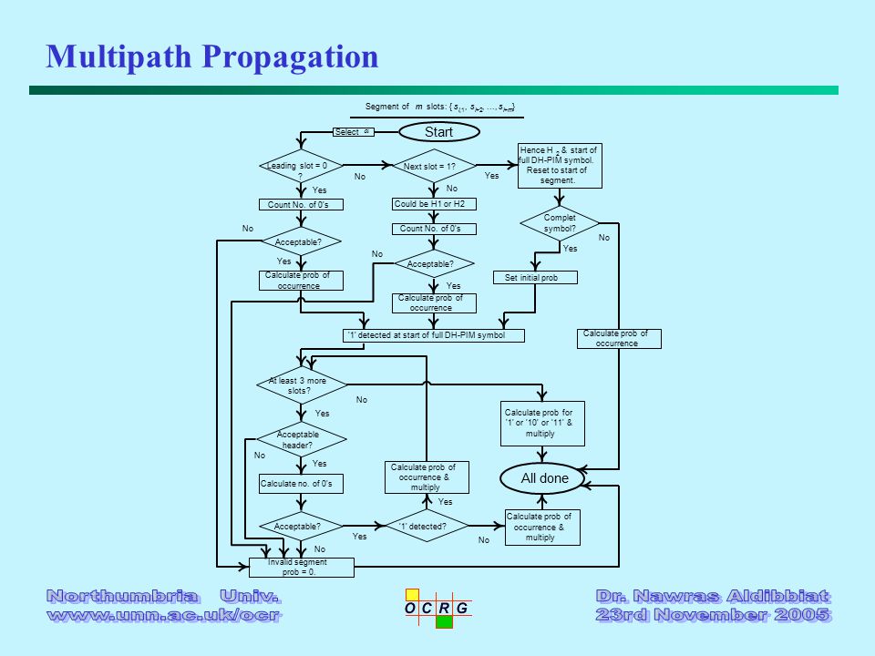
Multipath Propagation

45
0123456789 0 1 2 3 4 5 6 7 8 x 10 -6 T s Cascaded system impulse response 32-DH-PIM 1, R b = 1 Mbps D T = 0.001 D T = 0.01 D T = 0.1 D T = 0.2 _____ __ ___ _........ Impulse Response

46
Diffuse Systems - Eye Diagram NDS = 0.01 12345678 0 0.2 0.4 0.6 0.8 1 1.2 x 10 -3 NDS = 0.1 12345678 0 0.2 0.4 0.6 0.8 1 x 10 -3

47
Optical Power Requirements

48
10 -3 10 -2 10 10 0 -10 -8 -6 -4 -2 0 2 4 6 8 10 12 RMS delay spread / T b Normalised optical power requirements (dB) DH-PIM 1 2 DPIM PPM OOK L = 32 Optical Power Requirements - cont.
 DH-PIM 1 2 DPIM PPM OOK L = 32 Optical Power Requirements - cont.")
49
Optical Power Penalty

50
10 -3 10 -2 10 10 0 0 2 4 6 8 12 14 RMS delay spread / T b Optical power Penalty (dB) DH-PIM 1 2 DPIM PPM OOK L = 32 Optical Power Penalty - cont.
 DH-PIM 1 2 DPIM PPM OOK L = 32 Optical Power Penalty - cont.")
51
Conclusions Compared with PPM and DPIM, DH-PIM offers: –shorter symbol length –higher transmission rate –less bandwidth requirements –simple slot synchronisation –built-in symbol synchronisation DH-PIM offers improved error performance compared with OOK, but inferior to PPM and similar to DH-PIM

52
Conclusions - cont. The optimum system performance in terms of optical power and bandwidth requirements is achieved at DH-PIM (L=16, =1), DH- PIM (L=64, =2) and DPIM L = 16. A trade-off between the extent of artificial light interference rejection and the severity of baseline wander. Retransmission of DH-PIM symbols for 3 times or more gives significant improvement to the probability of errors at the expense of reducing the throughput
, DH- PIM (L=64, =2) and DPIM L = 16. A trade-off between the extent of artificial light interference rejection and the severity of baseline wander. Retransmission of DH-PIM symbols for 3 times or more gives significant improvement to the probability of errors at the expense of reducing the throughput.")
53
Final Remarks Acknowledgements: –Professor Fary Ghassemlooy (Associate Dean For Research) –Dr. R. McLaughlin (Sheffield Hallam University) Two MSc students are working on DH-PIM: –Wasiu Popoola: Equalisation –Olusegun Sanyaolu: Coding We’re seeking collaboration with staff or students from Informatics regarding mathematical analysis
 Two MSc students are working on DH-PIM: –Wasiu Popoola: Equalisation –Olusegun Sanyaolu: Coding We’re seeking collaboration with staff or students from Informatics regarding mathematical analysis.")
54
THANK YOU

Similar presentations


>")


