Download presentation
Presentation is loading. Please wait.

1
Car Monitoring System Team IPA Kirill Belyayev Amjad Chaudhry Arush Dhawan Aditya Kaundinya Bilal Yousufi

2
Introduction and Development Kit Amjad Chaudhry

3
In-Car Automation and Monitoring System Sensors are placed throughout a car that wirelessly send data back to a central terminalSensors are placed throughout a car that wirelessly send data back to a central terminal –Data displayed on LCD –Zigbee is used to transmit and receive Data –Visual Warnings will be given if a sensor detects something has fallen below the threshold.

4
Implementation We will use Zigbee technology to measure different components of a car and display the data on a main LCD screen.We will use Zigbee technology to measure different components of a car and display the data on a main LCD screen. –Tire Pressure –Temperature –Accelerometer –Proximity Sensor –Car Battery Voltage If any of the sensors detect a critical level our system will be used to provide a visual warning to the driver.If any of the sensors detect a critical level our system will be used to provide a visual warning to the driver.

5
Project Outline

6
Division of Labor Aditya and Amjad will work solely on software issues –A/D Converter –Zigbee Communication Kirill –Mainboard Design –Hardware/Software Implementation Will also work with Aditya and Amjad, with software implementation of hardware (I.e. LCD, Keypad, RS-232, User Interface) Arush and Bilal –Sensors’ schematic and design –PCB for Main Board and Sensors
 Arush and Bilal –Sensors’ schematic and design –PCB for Main Board and Sensors.")
7
Parking Sensors Tire Pressure Sensors Accelerometer Sensor Temperature sensors Battery voltage sensors LCD Screen KeypadSpeaker Main Terminal System Architecture

8
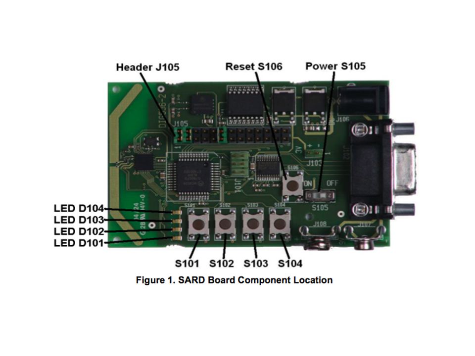
Development Kit Our development kit came with a programming environment, CodeWarrior. The kit also came with demo applications to be tested with our board to introduce the user to programming for RF applications. The board has: Two accelerometers, four switches and LEDs, a MC13192 transceiver, printed antenna, serial interface and MC9s08GT60 low-power MCU with 60KB of flash memory.

10
Software Aditya Kaundinya

11
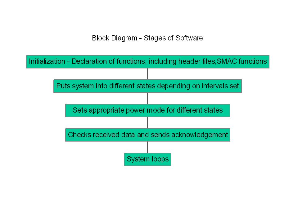
Software Overview Zigbee Communication Simple Media Access Controller Functions ANSI C based code used for developing RF applications. A/D Converter Implementation Used to convert continuous signals to digital numbers. The digital output can take different arithmetic forms. (Binary, Hexadecimal, etc.)
.")
12
Demo Software Our development kit came with demo code that allowed us to test our hardware. -Range Finder – Code that adjusted the number of blinking LED’s respective to the distance between the two boards. -UART Demo – Wireless transmits a user’s keystrokes to the terminal of another pc using the Zigbee transceivers.

13
Example Code (Range Detection) TRANSMIT STATE - case TX_STATE: /*Load the tx buffer with the ZigBee packet.*/ au8TxDataBuffer[0] = 'Z'; au8TxDataBuffer[1] = 'i'; au8TxDataBuffer[2] = 'g'; au8TxDataBuffer[3] = 'B'; au8TxDataBuffer[4] = 'e'; au8TxDataBuffer[5] = 'e'; sTxPacket.u8DataLength = 6; if (MCPSDataRequest(&sTxPacket) == SUCCESS) MLMERXEnableRequest(&sRxPacket,DELAY_COUNT); RECEIVE STATE - case RX_STATE: MLMERXEnableRequest(&sRxPacket,0); break;
![Example Code (Range Detection) TRANSMIT STATE - case TX_STATE: /*Load the tx buffer with the ZigBee packet.*/ au8TxDataBuffer[0] = Z ; au8TxDataBuffer[1] = i ; au8TxDataBuffer[2] = g ; au8TxDataBuffer[3] = B ; au8TxDataBuffer[4] = e ; au8TxDataBuffer[5] = e ; sTxPacket.u8DataLength = 6; if (MCPSDataRequest(&sTxPacket) == SUCCESS) MLMERXEnableRequest(&sRxPacket,DELAY_COUNT); RECEIVE STATE - case RX_STATE: MLMERXEnableRequest(&sRxPacket,0); break;](http://images.slideplayer.com/16/5156973/slides/slide_13.jpg "Example Code (Range Detection) TRANSMIT STATE - case TX_STATE: /*Load the tx buffer with the ZigBee packet.*/ au8TxDataBuffer[0] = Z ; au8TxDataBuffer[1] = i ; au8TxDataBuffer[2] = g ; au8TxDataBuffer[3] = B ; au8TxDataBuffer[4] = e ; au8TxDataBuffer[5] = e ; sTxPacket.u8DataLength = 6; if (MCPSDataRequest(&sTxPacket) == SUCCESS) MLMERXEnableRequest(&sRxPacket,DELAY_COUNT); RECEIVE STATE - case RX_STATE: MLMERXEnableRequest(&sRxPacket,0); break;")
14
SMAC Functions MLMESetMC13192Outp utAdjust Adjusts the output power of the transmitter(0-15) MLMEHibernateRequestDisables Clock Output MLMEWakeRequestBrings radio out of low power mode MLMERXEnableRequestPlaces radio in receive mode sRxPacket->pu8Data[3]Reads power value from third byte of data packet
![SMAC Functions MLMESetMC13192Outp utAdjust Adjusts the output power of the transmitter(0-15) MLMEHibernateRequestDisables Clock Output MLMEWakeRequestBrings radio out of low power mode MLMERXEnableRequestPlaces radio in receive mode sRxPacket->pu8Data[3]Reads power value from third byte of data packet](http://images.slideplayer.com/16/5156973/slides/slide_14.jpg "SMAC Functions MLMESetMC13192Outp utAdjust Adjusts the output power of the transmitter(0-15) MLMEHibernateRequestDisables Clock Output MLMEWakeRequestBrings radio out of low power mode MLMERXEnableRequestPlaces radio in receive mode sRxPacket->pu8Data[3]Reads power value from third byte of data packet")
16
A-D Converter Tire pressure sensor gives an analog voltage value. The output pin of the sensor is connected to one of the 8 A-D converter pins on the microcontroller. The voltage signal from the sensor is converted to a binary number using the microcontroller. The voltage-pressure relation below is used to convert the digital value into the corresponding pressure value.

17
Immediate Software Goals Goal 1 – by 03/03/2008 Understand all the SMAC functions by next Monday. Simultaneously work on writing code to control LED’s using the pushbuttons. Goal 2 – by 03/15/2008 Connect tire pressure sensor to the A/D converter on the development board. Write software to output the correct air pressure from the A/D converter.

18
Main Board Kirill Belyayev

19
Main Board Schematic

20
Microprocessor MC9S08GT60 Six Different General I/O Ports: Port A has keyboard interrupts Port B has A/D Converter inputs Port C has SCI2 and I 2 C interfaces Port D has Timer/PWM module Port E has SCI1 and SPI interfaces

21
RF Data Modem MC13192 SPI pins for on-board communication RF input/output pins General purpose I/O pins Interrupt, Reset, Rx/Tx Enable pins External clock pins

22
Serial Communication Interface Max3232 – SCI Driver and Receiver

23
Keypad 12 Keys – 7 pins Rows have pull up resistors and used as outputs Columns used as inputs

24
LCD Interface Two NJU6676 Drivers 64x132 pixels each Parallel or Serial Internal power supply circuit (not used)
")
25
Sensor Schematics Arush Dhawan

26
Sensor Schematic Tire Pressure Chip - MPX4250 –Operates at 5V Max Input of MC9S08 is 3.6V –Attenuator –Readjust Transfer Function in Software –Sensor Chips are interchangeable, the only thing that will need to be adjusted the attenuator and software. Temperature – FM20P5X – 3.3V X-Y Accelerometer – MMA1260D - 5 V Z Accelerometer – MMA6261Q 3.3V Proximity Sensor – Sharp GP2Y0A21YK - 3.3V

27
Tire Pressure Chip

28
Temperature Chip

29
Z Accelerometer Chip

30
X-Y Accelerometer

31
Proximity Sensor

32
PCB Design and Logistics Bilal Yousufi

33
PCB Design – Revision 1 Altium Designer 1 st Revision by March 1 st R –2 Boards Mainboard –Power Source: 12V Battery with DC-DC Buck Converter. »Components Operate between 3.3V – 12V Tire Pressure Board

34
PCB Design – Revision 2 2 nd Revision by Milestone 2 –Mainboard –Tire Pressure, Temperature, 3-axis Accelerometer Board, and more if time permits Sensor Boards will be powered by batteries. –We will try to lower power consumption as much as possible –Test Power Consumption, based on transmission intervals Ruggedized Casing –RF Data Modem 3 rd Revision by Expo –More Sensors (Voltage or Fluid Level) –More Mainboard Functions Storage Color LCD 4 Layer Boards from 4pcb.com –Routing on Outside –Inner Layers will be Voltage (3.3V) and Ground –A couple of Sensors use 5V, we might split the voltage layer, or use a boost converter.
 –More Mainboard Functions Storage Color LCD 4 Layer Boards from 4pcb.com –Routing on Outside –Inner Layers will be Voltage (3.3V) and Ground –A couple of Sensors use 5V, we might split the voltage layer, or use a boost converter..")
35
Long Range RF Modem Car – PC Link that can send Data (i.e. Racetrack, Test drive) 40 Mile Range Monitor Sensor Data on Computer Will be implemented in the second revision of the design RS-232 Link (Already on Mainboard) Implementing Software will be the main issue We don’t have experience with creating packet structure
 40 Mile Range Monitor Sensor Data on Computer Will be implemented in the second revision of the design RS-232 Link (Already on Mainboard) Implementing Software will be the main issue We don’t have experience with creating packet structure.")
36
Power Mainboard –3.3V, 5V –Input of 9V for 1 st PCB Revision –Input of 12V for 2 nd PCB Revision (Car Battery) Voltage Regulators to Step Down to 3.3V, and 5V Boost Converter to 15 V Sensor –3.3V Power Source –Converters for Sensor Chips
 Voltage Regulators to Step Down to 3.3V, and 5V Boost Converter to 15 V Sensor –3.3V Power Source –Converters for Sensor Chips")
37
Power Our first PCB Revision will not be wireless and have a 9V Source. We will be using the power adapters from our development kit. We will be using 9V with Voltage Regulators at 5V and 3.3V Our second PCB Revision will focus on power conservation, and the sensor modules will be run by batter

38
LCD Interface Proper Operation of LCD, needs 5 discreet voltages Voltages Range from 3.3V to –12V Logic – 3.3V GND – 0 V On/Off Voltages for LCD Pixels Bias Voltage is -12V (Pixels, Contrast)
")
39
Power - LCD Interface Power Circuit for Display Adjusts Contrast On/Off Voltages for Pixels

40
Updated Timeline

41
Parts

42
Questions?

Similar presentations


>")


 Jeff Shin Tyler Stubbs Paul Kasemir Pavel Mayyak.>")


