Download presentation
Presentation is loading. Please wait.

1
Wind Instrument Testing Apparatus Project WITAP Team: Rob Koch Andy Lawrence

2
Background An anemometer is a device used to measure wind speed. Commonly it is mounted on towers or inaccessible places. The data generated from these devices is used to assess the feasibility of wind power generation at that site.

3
Problem Statement Vermont Technical College has an Anemometer Loan Program using NRG anemometers. The anemometers need to be checked periodically for function and calibration.

4
Type of Anemometer to be Tested: Cup Anemometer: Simplest type of anemometer Air flow past the cups turns the spindle outputting a varying frequency signal proportional to the wind speed Standard models use a sensitive 4-pole magnet Type to be calibrated in the device

5
Our proposed solution is to build an airflow chamber that can put out a steady and consistent air velocity to an open air anemometer and save cost. A workshop device needs to be developed with an effective range of air flow control and data acquisition capability to assess anemometer operation and accuracy. Solution Statement

6
System Requirements Non-Turbulent Air Flow Output Non-Turbulent Air Flow Output Wind Velocity Controlled to ± 0.2 m/s Wind Velocity Controlled to ± 0.2 m/s Air Flow Capable of 1 to 20 m/s (45mph) Air Flow Capable of 1 to 20 m/s (45mph) Accuracy and Consensus of Measured Data Accuracy and Consensus of Measured Data Repeatability of Results Repeatability of Results
 Air Flow Capable of 1 to 20 m/s (45mph) Accuracy and Consensus of Measured Data Accuracy and Consensus of Measured Data Repeatability of Results Repeatability of Results")
7
Work so Far Design and Build Chamber Test General Wind Flow Capability of System Test Specific Airflow Characteristics of Chamber Design and Build Mechanical Features Design and Build Electronic Control System Test, Test, Test,

8
Solution A wind tunnel with reduced outlet for higher velocity Powered by constant-speed 120VAC fan Wind speed can be varied with shutters at inlet to fan Wind speed is measured with a pitot tube connected to a pressure sensor that outputs 0 to 4V DC Wind speed is controlled by using the 0 to 4 V signal and controlling the shutters accordingly Shutter control system consists of a Motorola HC08 microcontroller, a Reversible DC motor controller, and a DC motor connected to the shutters.

9
Test Sequence PC HC08 Pressure Sensor Converted Setpoint Value 0 to4v Signal Time Delay Setpoint = Velocity Yes No Acquire Data From Anemometer and Sensor Adjust Damper New Setpoint Compare Data

10
HC08 RS232 Differential Pressure Sensor H Bridge Motor Controller 5V GND 0.25-4V PWM Signal A/D ……………………. …………………… Damper Motor + - Dampers Setpoint Entry Fan Dampers Chamber PC Wind Outlet Pitot Tube Air hoses to sensor

11
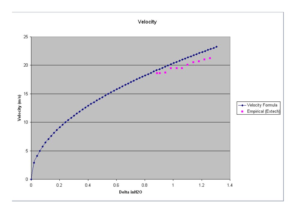
Outlet υ = √2g(P t -P s )/γ General Equation g = acceleration of gravity, γ = specific weight of air υ = √P v (1.289) 2 Pv (Pa), υ (m/s) υ = √P v (4005) 2 Pv (inH 2 O), υ ( ft/min) P t = Total Pressure P s = Static Pressure P v = Velocity Pressure = (P t -P s ) υ = velocity PtPsPtPs Measuring Air Velocity using Velocity Pressure Velocity Pressure uses the differential pressure in the output to determine velocity P t tap P s tap Manometer Chamber Dampers Fan Simulated Wind Air Flow Pitot-Static Tube
/γ General Equation g = acceleration of gravity, γ = specific weight of air υ = √P v (1.289) 2 Pv (Pa), υ (m/s) υ = √P v (4005) 2 Pv (inH 2 O), υ ( ft/min) P t = Total Pressure P s = Static Pressure P v = Velocity Pressure = (P t -P s ) υ = velocity PtPsPtPs Measuring Air Velocity using Velocity Pressure Velocity Pressure uses the differential pressure in the output to determine velocity P t tap P s tap Manometer Chamber Dampers Fan Simulated Wind Air Flow Pitot-Static Tube")
12
Pitot Tube Function ▪ When a moving fluid is caused to stop because it encounters a stationary object, a pressure is created at that point that is greater than the pressure in the fluid stream. ▪ The magnitude of this increased pressure is related to the velocity of the moving fluid. ▪ The pitot tube measures the stagnation pressure due to the deceleration of the flowing fluid. Stagnation pressure

13
Costs

14
Time breakdown

15
Questions?

16
System Requirements Air Flow Capable of Up to 20 m/s (45mph) Non-Turbulent Air Flow Output Constant Air Pressure at Setpoints Non-Intrusive Sensor Accuracy and Consensus of Measured Data Repeatability of Results
 Non-Turbulent Air Flow Output Constant Air Pressure at Setpoints Non-Intrusive Sensor Accuracy and Consensus of Measured Data Repeatability of Results")
17
motor Fan airflow controlled vent manometer damper motor motor controller HC08 hot wire sensor Chamber output opening magnahelic gauge reader System Diagram

18
System Modeling Considerations Whether flow is adiabatic Effective pressure difference needed Whether present model is relevant Type of flow, need for baffles Sensitivity requirements of control/monitoring instruments For adiabatic flow of a compressible fluid (air) from inside a chamber through an opening the velocity is given by: υ2 = {(2gp 1 /γ 1 )(k/k-1)[1-(p 2 /p 1 ) (k-1)/k ]} 1/2 k = adiabatic exponent = 1.40 for air γ= specific weight = 11.81N/m3 p1 = pressure in chamber (Pascals), p2 = atmospheric (Pascals)
![System Modeling Considerations Whether flow is adiabatic Effective pressure difference needed Whether present model is relevant Type of flow, need for baffles Sensitivity requirements of control/monitoring instruments For adiabatic flow of a compressible fluid (air) from inside a chamber through an opening the velocity is given by: υ2 = {(2gp 1 /γ 1 )(k/k-1)[1-(p 2 /p 1 ) (k-1)/k ]} 1/2 k = adiabatic exponent = 1.40 for air γ= specific weight = 11.81N/m3 p1 = pressure in chamber (Pascals), p2 = atmospheric (Pascals)](http://images.slideplayer.com/16/5148706/slides/slide_18.jpg "System Modeling Considerations Whether flow is adiabatic Effective pressure difference needed Whether present model is relevant Type of flow, need for baffles Sensitivity requirements of control/monitoring instruments For adiabatic flow of a compressible fluid (air) from inside a chamber through an opening the velocity is given by: υ2 = {(2gp 1 /γ 1 )(k/k-1)[1-(p 2 /p 1 ) (k-1)/k ]} 1/2 k = adiabatic exponent = 1.40 for air γ= specific weight = 11.81N/m3 p1 = pressure in chamber (Pascals), p2 = atmospheric (Pascals)")
19
P2 2 υ2 flow Pressurized Chamber Control variable Ideally adiabatic ( 1= 2) Atmospheric Formula for system analysis using differential pressure between chamber and atmosphere υ2 = {(2gp1/γ1)(k/k-1)[1-(p2/p1)(k-1)/k]} 1/2 Model for System Analysis Using the Formula P1 1 υ1=0
![P2 2 υ2 flow Pressurized Chamber Control variable Ideally adiabatic ( 1= 2) Atmospheric Formula for system analysis using differential pressure between chamber and atmosphere υ2 = {(2gp1/γ1)(k/k-1)[1-(p2/p1)(k-1)/k]} 1/2 Model for System Analysis Using the Formula P1 1 υ1=0](http://images.slideplayer.com/16/5148706/slides/slide_19.jpg "P2 2 υ2 flow Pressurized Chamber Control variable Ideally adiabatic ( 1= 2) Atmospheric Formula for system analysis using differential pressure between chamber and atmosphere υ2 = {(2gp1/γ1)(k/k-1)[1-(p2/p1)(k-1)/k]} 1/2 Model for System Analysis Using the Formula P1 1 υ1=0")
21
motor Fan airflow controlled vent damper motor motor controller HC08 hot wire sensor Chamber output opening Electrical Systems Diagram PC

22
Manometer and Magnehelic - measure differential pressure in inches water column Measurement Devices Used

23
Extech and Dwyer Wind Measurement Device- measure air flow directly in units of m/s Measurement Devices Used

24
Possible Measurement Device to be Used: Hot Wire Anemometer: Use a very fine wire heated to a temperature above ambient Air flow past the wire has a cooling effect on the wire The electrical resistance of the wire is dependent on the temperature A relationship can be obtained between the resistance of the wire and the velocity of the air flow. High frequency response; used to study turbulent flow and rapid velocity fluctuations. Can give an analog voltage output

25
Hot Wire Anemometer- this sensor measures volume of air flow electronically through the use of a thermistor, resistive heat element with positive temperature coefficient, and bridge circuit Hot Wire Anemometer Schematics

26
Chain of Events Design and Build Chamber Test General Wind Flow Capability of System Test Specific Airflow Characteristics of Chamber Design and Build Mechanical Features Design and Build Electronic Control System Test, Test, Test,

27
Costs

28
Time breakdown

29
Fan Dayton Duct Fan 4C661 18.5 inch effective opening 21 inch base Max rpm@ 1HP: 1988 Single phase Dayton motor 6K760A 1HP, Capacitor start, 1725 rpm,

30
What types of methods are used for calibrating wind speed sensors The cup anemometer is the type to be calibrated by this apparatus Wind tunnels Problems with wind tunnels?

Similar presentations


 and low turbulence intensity.>")


