Download presentation
Presentation is loading. Please wait.

1
ME 322: Instrumentation Lecture 32 April 10, 2015 Professor Miles Greiner

2
Announcements/Reminders HW 10 due Monday I’m having trouble getting the date for the sample lab so I will post the new lab instructions (including L10PP), the sample data, and the sample report by the end of today… (sorry for taking so long) Marissa Tsugawa will hold a problem review session on Sunday – Will email time and place Next week: Lab 10 Vibrating Beam Did you know? – HW solutions are posted on WebCampus – Exam solution posted outside PE 213 (my office) Help wanted (see me greiner@unr.edu)greiner@unr.edu – Spring 2016: ME 322 Lab Assistant
 Help wanted (see me – Spring 2016: ME 322 Lab Assistant.")
3
Cylinder in Cross Flow (unsteady) Speed is reduced in the wake region Instability of steady flow causes periodically-shed vortices – Karman Vortex Street Karman Vortex Street Figure shows unsteady speed measured by a probe in wake – Fairly regular oscillations, period P ~ 0.01/6 = 0.0017 sec – Peak oscillatory frequency of f = 1/P ~ 600 Hz Broad spectrum of frequencies – Can a Pitot probe measure oscillations at these high frequencies? How to measure rapidly changing speeds? V∞V∞ Velocity Probe

4
Strouhal Number V∞V∞ D Q f Q

5
Example

6
How to measure Rapidly Varying Speed? Pressure Method – Pitot probes transmit pressure to transducers using tubes – This is ok for slowly varying speeds – At high frequencies, pressure response at transducer is attenuated and delayed compared to probe (2 nd order system) Heat Transfer Method – Hot Wire or Hot Film probe Very small wire or metal plated quartz on a support fork – Electrically heated surface – Heat transfer to the surrounding fluid increases with fluid speed – Two modes: Constant Current (film get cooler when speed increases) Constant Temperature (more power is required to maintain temperature at high speed)
 Heat Transfer Method – Hot Wire or Hot Film probe Very small wire or metal plated quartz on a support fork – Electrically heated surface – Heat transfer to the surrounding fluid increases with fluid speed – Two modes: Constant Current (film get cooler when speed increases) Constant Temperature (more power is required to maintain temperature at high speed).")
7
Hot wire/film circuit Circuit VOVO V ∞ T ∞ I VEVE I T S R S R2R2

8
How to find T S ?

9
Constant Current Mode VOVO V ∞ T ∞ I VEVE I T S R S R2R2 V0V0 V∞V∞

10
Constant Temperature Anemometer (CTA) Incorporates hot sensor into a Wheatstone bridge If speed V ∞ increases, T S and R S “start” to go down This decreases V Bridge, but Feedback amplifier (op-amp) very quickly increases V O to increase current to sensor and restore its temperature and resistance (R S = R R ) The current and power to the sensor adjusts to make its temperature constant Output is V CTA (voltage across sensor) V∞V∞ V Bridge V CTA T S R S R R
 Incorporates hot sensor into a Wheatstone bridge If speed V ∞ increases, T S and R S start to go down This decreases V Bridge, but Feedback amplifier (op-amp) very quickly increases V O to increase current to sensor and restore its temperature and resistance (R S = R R ) The current and power to the sensor adjusts to make its temperature constant Output is V CTA (voltage across sensor) V∞V∞ V Bridge V CTA T S R S R R")
11
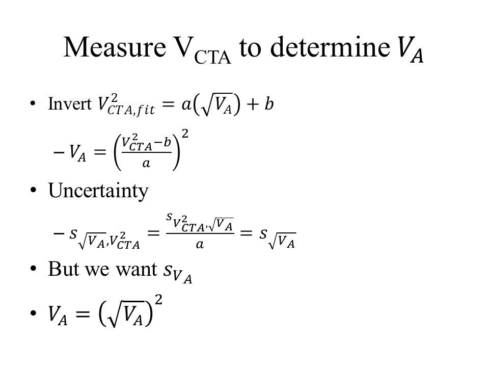
CTA Transfer Function Constants

12
Hot Film System Calibration The fit equation V CTA 2 = aS A 0.5 +b appears to be appropriate for these data. The dimensional parameters are – a = 1.366 volts 2 s 1/2 /m 1/2 and – b = 2.2057 volts 2

13
Lab 11 Unsteady Speed in a Karman Vortex Street Use the same wind tunnels as Lab 6 – Sign up for 1.5 hour periods with your partner in lab next week Two steps – Statically calibrate hot film CTA using a Pitot probe – Measure unsteady speed downstream from a cylinder of diameter D Perform spectral analysis and find frequency with peak amplitude, f P Measure “steady” speed without cylinder V Calculate St D = Df P /V and compare to expectations

14
Setup D Tube P Static Total + - IPIP Variable Speed Blower Plexiglas Tube Pitot-Static Probe V C 3 in WC Barometer P ATM T ATM CTA myDAQ Cylinder V CTA

15
Before Experiment Construct VI (formula block) Measure P ATM, T ATM, and cylinder D Find and for air Air Viscosity from A.J. Wheeler and A. R. Ganji, Introduction to Engineering Experimentation, 2 nd Edition, Pearson Prentice Hall, 2004, p. 430.

16
Fig. 2 VI Block Diagram

17
Fig. 1 VI Front Panel

18
Calibrate CTA using Pitot Probe Remove Cylinder Align hot film and Pitot probes (carefully) – 4 probes cost $600 Measure V CTA,AVG and I Pitot for different blower speeds
 – 4 probes cost $600 Measure V CTA,AVG and I Pitot for different blower speeds")
19
Calibration Measurements and Calculations

20
Table 2 Calibration Data The initial and final no-wind hot film voltages and Pitot transmitter currents are the same.

21
Standard Error of the Estimate x x x x x x x x V CTA 2

24
Cylinder in cross flow Wake: region of reduced speed Frequency Strughold #: For Constant Page 360 to 361 Measure flow rate in a pipe

25
Example A car antenna D = 0.25 in and car s=60 mph What will the frequency of the shed vortices be?

26
Before we used: Pressure Method Pito-probe/pressure transmitter (too slow) Heat transfer method: -hot film or hot wire probe -small electrically heated surface Probe: Acid etched wire (hot wire) -small but brittle Metal plated quartz cylinder (hot film).
 Heat transfer method: -hot film or hot wire probe -small electrically heated surface Probe: Acid etched wire (hot wire) -small but brittle Metal plated quartz cylinder (hot film).")
27
Probe electrical resistance heating → Can measure I, V 0 Q [watts] Heat is mostly dissipated by convection For small cylinders in cross flow
![Probe electrical resistance heating → Can measure I, V 0 Q [watts] Heat is mostly dissipated by convection For small cylinders in cross flow](http://images.slideplayer.com/14/4182312/slides/slide_27.jpg "Probe electrical resistance heating → Can measure I, V 0 Q [watts] Heat is mostly dissipated by convection For small cylinders in cross flow")
28
How to find T S : Wire resistance changes with its temperature T S : α ≡ material property So theoretically by measuring: A, I, V 0, & known α.

29
Tow modes of operation: 1) Constant current V E ≡ constant & R 2 >> R S As U↑, h↑, T S ↓, R S ↓ Problem: T S must reach equilibrium with surroundings. Takes time Max frequency Response

30
2) Constant Temp Anemometer (CTA) Uses electronic feedback (op-amp) to very V E so T S (and R S ) stay constant. Wheat stone bridge circuit

Similar presentations


>")


 and low turbulence intensity.>")


 Time & Location: 2:30P - 3:20P MWF 218 MLH Office Hours: 4:00P – 5:00P MWF 223B-5 HL Instructor:>")
