Download presentation
Presentation is loading. Please wait.

1
Technion – Israel Institute of Technology Department of Electrical Engineering High Speed Digital Systems Lab Project performed by: Safi Seid-Ahmad Emile Ziedan Project supervised by: Michael Itzkovitz

2
Building a prototype of a device that is capable of detecting object colors for the use of blind people. The system informs the user of the color by a voice message. This device should be: Simple to use. Portable. Inexpensive.

3
There are various representation models for colors. We use RGB model. RGB model : every visible color can be represented as a combination of 3 basic colors: Red, Green and Blue. For example: RedGreenBlue Orange25512864 Yellow255 0

4
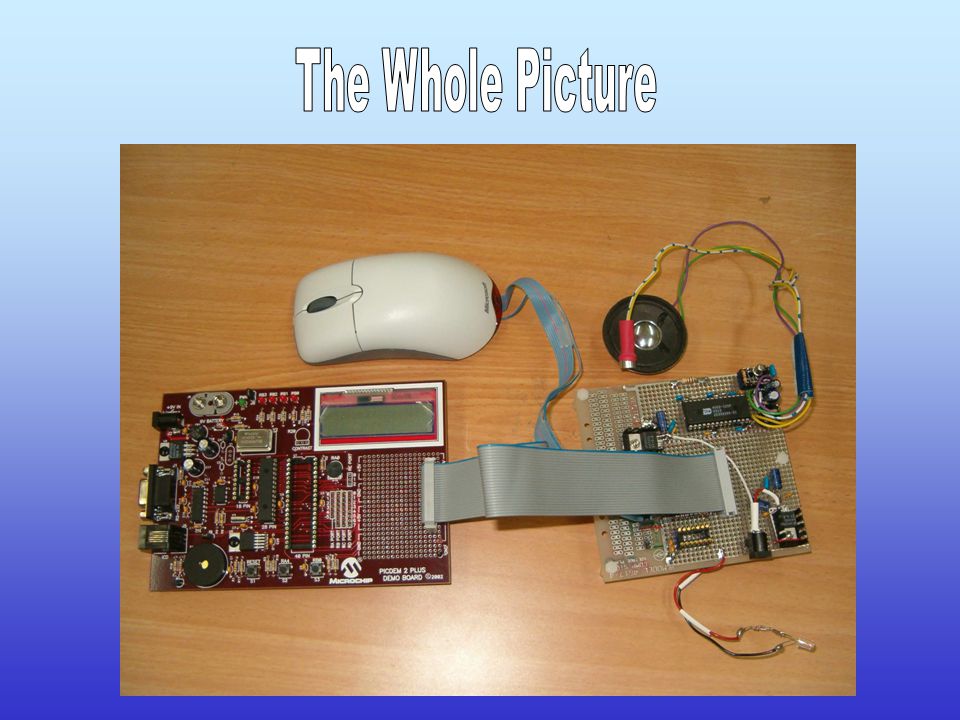
Light Source Light Source Driver Light Analyzer Driver Light Analyzer RGB Calculation Red -Freq Green -Freq Blue -Freq Color Determination Red Green Blue Voice Memory Speaker Analog signal Voice Memory Driver Object Orange Speaker driver Microcontroller

5
The user presses the operation button. Measurements are performed for each of Red, Green and Blue channels of the TCS. RGB values are calculated in the micro controller. According to an inner look table, the color is determined. A message declaring the detected color is played.

6
‘White Calibration’ is used to counteract any offsets or environmental effects. When do we need to perform calibration? when changing the light sensor. when changing it’s package. when changing the light source.

7
How do we perform the calibration? Our method is calculating the period of time in which we count 255 pulses on the TCS output for a white object. This is done for each channel (R, G & B) separately. The number of pulses on TCS output during the above period is between 0 and 255.
 separately. The number of pulses on TCS output during the above period is between 0 and")
8
PIC DEM 2 PLUS : This is a programming environment for PIC. The programming of the PIC is done in a c-like language, using MPLAB software. It’s possible to run the program on the board as stand-alone, or in a debugging mode controlled by MPLAB.

10
Hardware includes: TCS230: A programmable color light-to frequency converter. White led as a light source for TCS230. PIC18F252: High Performance, Enhanced FLASH Microcontroller. ISD4002: Single-chip voice record/playback solution. Microphone/Speaker circuits for record/playback.

11
TCS230 output is a square wave with frequency directly proportional to light intensity. TCS reads an 8 x 8 array of photodiodes. 16 having blue filters, 16 green filters, 16 red filters, and 16 photodiodes are clear with no filters. The result is that we can measure the intensity of the red, green and blue components of color.

12
TCS230 PIC18F252 ISD4002 Light Source MicrophoneSpeaker

13
TAOS TCS230: A programmable color light-to-frequency converter Vdd = 5 V Idd = 2 mA (Power-on mode) 7 uA (Power-down mode)
 7 uA (Power-down mode)")
14
MICROCHIP PIC18F252 High Performance, Enhanced FLASH Microcontroller Vdd = 5 V Idd = 0.5 – 1.5 mA Supports SPI protocol Memory: Flash32 KB On-chip RAM1536 B Data EEPROM256 B

15
WINBOND ISD4002: Single-chip voice record/playback solution Vcc = 3.3 V Icc = 15 mA (Playback) 25 mA (Record) Isb = 1 uA (Standby) 120 seconds duration SPI interface
 25 mA (Record) Isb = 1 uA (Standby) 120 seconds duration SPI interface")
16
There were two major problems in dealing with the TCS230 (the color sensor): The TCS230 is very sensitive to the environment light condition, so it should receive the light that is only reflected from the object. Since it is very sensitive, we need a light source that is as stable as possible, and contains almost all the visible spectrum of the light.

17
The solutions that we implemented are: We are using the package of a PC optical mouse, since it is suitable to our purpose – we put the TCS230 instead of the mouse light sensor… We used a WHITE LED – it is the ultimate choice we have seen…

20
Two modules used to control each one of the chips: TCS and ISD. Three main programs: A program for calibration A program for recording messages The main program of detecting colors The first two programs are used to configure the device, while the third is used for normal operation.

21
It is used to perform the calibration. It interfaces through USART connection to a computer (using Telnet). The user is asked to put the mouse on a white object, and then press the operation button. The periods for measurement on each channel will be displayed on the Telnet terminal. These values should be placed in the color detection program.
. The user is asked to put the mouse on a white object, and then press the operation button. The periods for measurement on each channel will be displayed on the Telnet terminal. These values should be placed in the color detection program..")
22
A program for recording messages of the color names in the ISD4002. The interface here is also through Telnet. Before recording each color the user should press the operation button. Next press plays the message, then there are two optional presses: one for recording next massage, and the other for recording the same message again.

23
The user puts the mouse on the target object and presses the operation button. The color is detected. A suitable message telling the detected color is being played. Additional telnet interface shows the exact RGB values of the object color.

25
In this project we explored the world of color detection, which is still an open field of research. We dealt with problems of calibration, sensitivity to light source, and measuring real RGB values of the color. This makes the project open for future developments of detecting real colors and processing them.

26
Enabling addition of predefined colors to the device interactively. Performing a white calibration by a single button, without the need to reprogram the device. The above can be accomplished easily if we use a flash memory that can be updated by the program.

27
The device is best for the usage of blind and color blind people. It can be used by children who are still learning color names. Since we can measure real RGB values, it can be also used by any application that compares exact colors.

28
Printed circuit design. Using a small package for the light sensor which include the whole system also. Using a battery as power supply. Power should be supplied to the light source and the speaker only when needed. This can be done by using electrical switches.

Similar presentations


 Jacob Dionne (CSE) Adam Montalbano (CSE) Jeffrey Newton (EE) Team Kelly Preliminary.>")


 Group Members: Keiichi McGuireHenry Pham Marc TakamoriScott Spiro.>")


