Download presentation
Presentation is loading. Please wait.

1
By: Alex Sowa Electrical Projects April 10 th, 2013

2
When I am riding my motorcycle at night, I often wish I had more lights. The more visible you are, the safer you are. I decided to build a do-it-yourself kit that can be mounted anywhere on your motorcycle. Kits like this are already offered, but are often expensive. Most other kits don’t allow you to change the color of the LEDs or create different blinking patterns. That is why I decided to build my own, that way I can completely customize it and also have the option of reprogramming it in the future to do different things.

3
DIY LED Kits

4
You can choose how many LEDs you want in your kit Strip of 30 LEDs on left side of bike and 30 on the right side each controlled by its own pushbutton Extremely bright Visible from 20m away Simple user interface Comes with 3M adhesive Flexible Waterproof LEDs Long life span 50,000+ hours

5
12V 2A maximum per LED (RGB) Every 3 LEDs are cutable without damaging the rest of the strip Comes with 3M adhesive Flexible Waterproof LEDs
 Every 3 LEDs are cutable without damaging the rest of the strip Comes with 3M adhesive Flexible Waterproof LEDs")
8
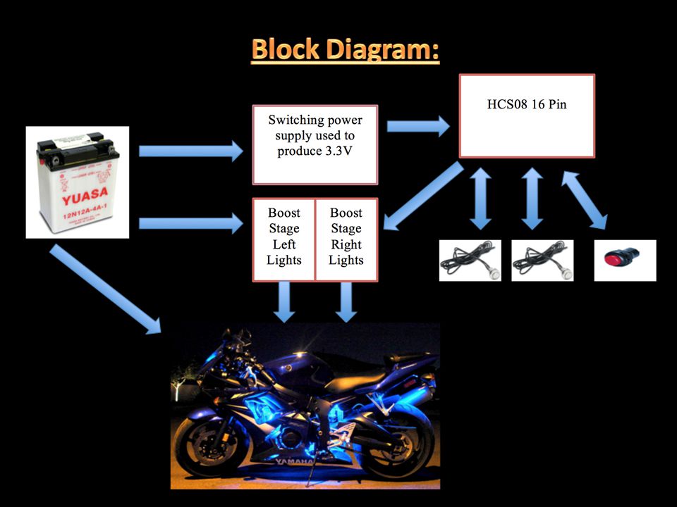
Switching power supply used to produce 3.3V How is this different from a voltage regulator circuit like the TIP122? Instead of using resistors, the LM2674 uses an inductor which, under ideal conditions has no resistance. Therefore when there is a voltage drop across the inductor, it stores the energy the magnetic field, unlike a resistor which dissipates it as heat. Eliminating the resistor is what makes this circuit more complex and very efficient. Now lets take a brief look at the complex circuitry inside the LM2674-3.3 VCC is the input to the microcontroller

9
The LM2674 is very efficient because of the fixed out it has and it is offered in three different packages, the 3.3V, 5V, and a adjustable output. The internal clock frequency along with the other complicated circuitry makes the circuit very accurate and the main reason I chose to use this chip is because of the wide range of input voltages since the voltage across the battery on my motorcycle is constantly changing when it is running.

10
It is important to note that the efficiency of this circuit depends upon selecting the right component values according to the different graphs and using one of the specified parts.

15
Boost Stage to produce 2A The reason this surface mount chip was chosen is because of the the wide range of tolerances it allows for the inputs and also the incredibly high output current which is exactly what I need for the LEDs.

16
The minimum voltage it takes to turn device on, and I am supplying it with the output of the LM2674, but its max ratings can take anywhere from -0.3V – 20V so it could also be powered from the motorcycle battery

17
This is the single most important characteristic about the UCC27511 (for my application). The extremely low output pull down resistance means that the amount of the heat that the internal transistor (will show in next slide

18
P = I 2 R = 1 2 A (Say Red LEDs are on) x 0.45Ω = 0.45W Compared to the 8 amps that you can sink from this device, that is hardly any heat. That is why this can be an extremely small surface mount chip

19
12V Input: White LED Current: 1.667A Blue Current: 0.622A Red Current:0.697A Green Current:0.725A Data sheet for LEDs specifies no more than 2A per color

20
The software will be structured by using a state machine. The power will be tied into the ignition switch, that way the circuit only comes on when the key is turned. The program will turn on and the counter will be at 0. The counter will increment by 1 each time the button is pressed and will reset at once it gets to 6. In order to produce different colors with the LEDs, the brightest of each color must be adjusted. This means that the duty cycle for each color (Red, green, and blue) must change each time a different color is chosen with the push button. ST1 ST3 ST2 ST0 ST4 ST6 ST5
 must change each time a different color is chosen with the push button. ST1 ST3 ST2 ST0 ST4 ST6 ST5.")
21
Get both strips of LEDs to light and have 6 different colors appear If I have time I will make a ribbon style connector to connect the LED strip to the circuit board which will be mounted underneath the seat Put silicone around ribbon connector to maintain waterproof connection Improve software to make LEDs blink in different patterns Strobe effect

22
Qty ValueValueSingle Qty $x100 Qty $ 1 16 Pin HCS080.1210 1 LM2674-3.33.02250 6 UCC275119.96800 1 120uF/35V cap0.5435 1 68uF/25V cap0.5232 110nF/50 cap 0.2915 1 Push Button0.3525 1 1N5817 Diode0.5340 1 150 uH inductor0.1814 1 60 RGB LEDs7500 $22.51$1,721

Similar presentations


 LED Dimmer Circuit>")

