Download presentation
Presentation is loading. Please wait.

1
Designing a Robot for Portable Raman Probe Positioning: The Robo-Scanner

3
Presentation Outline Objectives Introduction Hardware Design Software Design Design Alternatives Problems Encountered Future Goals

4
Main Objectives Main Objectives To design & build a functional prototype that will correctly position raman probe to scan pills & tissue Incorporate Matlab for positioning & data analysis Send Matlab outputs to microcontroller Write & implement Assembly code to translate Matlab code into motor movement Create model of different pill types

5
Introduction Raman Spectroscopy [1,2] Has numerous medical applicationsHas numerous medical applications Physics-based technique that detects chemical composition of a samplePhysics-based technique that detects chemical composition of a sample Each chemical has characteristic wavelength shiftEach chemical has characteristic wavelength shift Can relate the peaks in a Raman spectrum to specific chemicals & compare composition of a test sampleCan relate the peaks in a Raman spectrum to specific chemicals & compare composition of a test sample
![Introduction Raman Spectroscopy [1,2] Has numerous medical applicationsHas numerous medical applications Physics-based technique that detects chemical composition of a samplePhysics-based technique that detects chemical composition of a sample Each chemical has characteristic wavelength shiftEach chemical has characteristic wavelength shift Can relate the peaks in a Raman spectrum to specific chemicals & compare composition of a test sampleCan relate the peaks in a Raman spectrum to specific chemicals & compare composition of a test sample](http://images.slideplayer.com/16/4955135/slides/slide_5.jpg "Introduction Raman Spectroscopy [1,2] Has numerous medical applicationsHas numerous medical applications Physics-based technique that detects chemical composition of a samplePhysics-based technique that detects chemical composition of a sample Each chemical has characteristic wavelength shiftEach chemical has characteristic wavelength shift Can relate the peaks in a Raman spectrum to specific chemicals & compare composition of a test sampleCan relate the peaks in a Raman spectrum to specific chemicals & compare composition of a test sample")
6
Two Applications for Portable Raman

7
Raman Spectroscopy Portable Verax Raman spectrometer made by InPhotonics

8
Raman Spectroscopy Raman Spectroscopy

9
Main Components Erector sets Raman probe 68HC11 microcontroller Breadboard/circuitry Cameras DC step motors Printer railways

10
Hardware Design First Step: Build gantry frame using erector setsBuild gantry frame using erector sets Purchase & fasten c-channelsPurchase & fasten c-channels

11
Benefits of Gantry Design [3] Perform pick & place applications Provide better positioning accuracy Easier to program with respect to motion due to X,Y,Z coordinate system Less limited by floor space constraints
![Benefits of Gantry Design [3] Perform pick & place applications Provide better positioning accuracy Easier to program with respect to motion due to X,Y,Z coordinate system Less limited by floor space constraints](http://images.slideplayer.com/16/4955135/slides/slide_11.jpg "Benefits of Gantry Design [3] Perform pick & place applications Provide better positioning accuracy Easier to program with respect to motion due to X,Y,Z coordinate system Less limited by floor space constraints")
12
Hardware Design … Second Step: Disassemble printer componentsDisassemble printer components Mount X & Y railways onto frameMount X & Y railways onto frame

13
Hardware Design cont. Third Step : Create wheel mechanismCreate wheel mechanism Mount cameraMount camera Mount probe on Z-axisMount probe on Z-axis Gigaware® 1.3MP PC Camera

14
Mechanical Design DC step motors used from disassembled printers Change initial design concept of wheel mechanism To decrease drag & friction, remove rubber treadTo decrease drag & friction, remove rubber tread Reposition wheel on top of c-channel instead of insideReposition wheel on top of c-channel instead of inside

15
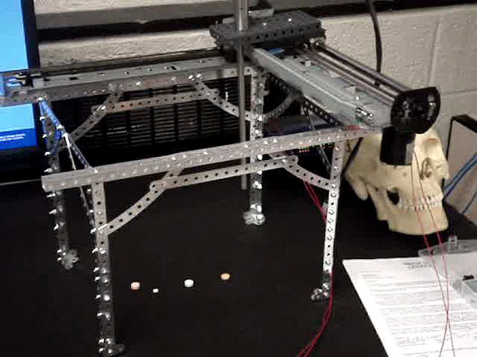
Final Product !

17
Network Overview 68HC11 Breadboard RS 232

18
Microcontroller Diagram

19
Electrical Components LM741CN Op Amp (All 3 inverting)
")
20
Software and Circuit Design

21
Wiring Diagrams

22
Software Design Second Step: Write code using Matlab Toolkits Wavelets (pre-processing)Wavelets (pre-processing) StatisticsStatistics Image processingImage processing Future Toolkits Camera calibration ~ 3D triangulation of 2 imagesCamera calibration ~ 3D triangulation of 2 images Image acquisition ~ live video feedImage acquisition ~ live video feed
Wavelets (pre-processing) StatisticsStatistics Image processingImage processing Future Toolkits Camera calibration ~ 3D triangulation of 2 imagesCamera calibration ~ 3D triangulation of 2 images Image acquisition ~ live video feedImage acquisition ~ live video feed")
23
Matlab GUI

24
Software Design Imaging Processing Toolkit to position robot Load video image from file (.jpg) from camera Load video image from file (.jpg) from camera Convert image to grayscale Convert image to grayscale Threshold image Threshold image Count distinct objects in image Count distinct objects in image Find center of each distinct object Find center of each distinct object Convert pixel location to robot location Convert pixel location to robot location Send location to HC11 by serial port Send location to HC11 by serial port
 from camera Load video image from file (.jpg) from camera Convert image to grayscale Convert image to grayscale Threshold image Threshold image Count distinct objects in image Count distinct objects in image Find center of each distinct object Find center of each distinct object Convert pixel location to robot location Convert pixel location to robot location Send location to HC11 by serial port Send location to HC11 by serial port")
25
Image Processing Results Original Image (with pills marked) Grayscale Image Threshold ImageCount Objects In Image *Results depend on lighting, photo conditions*
 Grayscale Image Threshold ImageCount Objects In Image *Results depend on lighting, photo conditions*")
26
Moving the Robot Check to see if starting from home position Move robot from home position to desired pill location Collect spectra (use separate software) Process software and output results Move robot from pill position to home Repeat for next pill
 Process software and output results Move robot from pill position to home Repeat for next pill")
27
Processing Details Preprocess Spectra Background SubtractionBackground Subtraction Remove noiseRemove noise Remove cosmic raysRemove cosmic rays Principal Component Analysis Reduce dimensionality of dataReduce dimensionality of data Algorithm Discriminant Function AnalysisDiscriminant Function Analysis Neural Network AnalysisNeural Network Analysis

29
Spectral Results

30
Testing Assembly Code

31
Problems Encountered Consider weight of raman probe in choosing initial robotic arm mechanics Devising efficient pulley system Weight of printer railways & motors High coefficient of friction between wheel & aluminum c-channel Software development & implementation Camera calibration Coordinate triangulation Time constraints Time constraints

32
Design Alternatives Possible Design Improvements: Construct robotic arm Addition of proximity sensors Swap microcontroller for new motion controller Incorporate AC servo motors in place of step motors Autonomous positioning

33
Future Goals Expand current design by incorporating more incorporating more sophisticated technologies sophisticated technologies Implement 3D triangulation using stereo camera calibrationImplement 3D triangulation using stereo camera calibration Combine functions with Nurse-Bot or similar applicationCombine functions with Nurse-Bot or similar application Use robot for scanning cancerous tissue samplesUse robot for scanning cancerous tissue samples Optimize portable robot design requirements for OR usageOptimize portable robot design requirements for OR usage Telepresence i.e. administer medicationTelepresence i.e. administer medication

34
Grand Finale Final Demo

36
References [1] Huang, Z., McWilliams, A., Lui, H., McLean, D.I., Lam, S. and Zeng, H., Near-infrared Raman spectroscopy for optical diagnosis of lung cancer. Int J Cancer, 2003. 107(6): p. 1047-52. [2] Cao, A., Pandya, A., Serhatkulu, G.K., Weber, R., Dai, H., Thakur, J.S., Naik, R., Naik, V., Auner, G.W., Rabah, R., and Freeman, D.C., A Robust Method for Automated Background Subtraction of Tissue Flourescence. Journal of Raman Spectroscopy, 2006 (in press). [3] http://www.robots.com/faq.php?question=gantry+robot http://www.robots.com/faq.php?question=gantry+robot
![References [1] Huang, Z., McWilliams, A., Lui, H., McLean, D.I., Lam, S.](http://images.slideplayer.com/16/4955135/slides/slide_36.jpg "and Zeng, H., Near-infrared Raman spectroscopy for optical diagnosis of lung cancer. Int J Cancer, (6): p [2] Cao, A., Pandya, A., Serhatkulu, G.K., Weber, R., Dai, H., Thakur, J.S., Naik, R., Naik, V., Auner, G.W., Rabah, R., and Freeman, D.C., A Robust Method for Automated Background Subtraction of Tissue Flourescence. Journal of Raman Spectroscopy, 2006 (in press). [3] question=gantry+robot question=gantry+robot.")
Similar presentations


 to binary (1 bit/pixel)>")


 Manoj Bhambwani Tameka Thomas.>")
