Download presentation
Presentation is loading. Please wait.

2
OutLine Overview about Project Wii Robot Escaper Robot Problems and Solutions Demo

3
Overview Our Project is a Robot Game Follower. We have two robots the first one carries the IR camera and controlled through the code and the second one carries the IR- LED and controlled wirelessly through the X-Bee Chip.

4
Overview cont’ The robot which carries the IR-Camera will detect the position of the IR-LED and through the code we will send commands to the motors to move to the IR-LED position.

5
Overview cont’ To make the game more fun the robot which is carrying the IR-LED will be controlled wirelessly to move any way you want.

6
Wii Robot

7
Hardware

8
Hardware System cont’ Tank Robot

9
Hardware System cont’ Wiimote Camera

10
Wiimote Camera.. PixArt* CMOS sensor consists of two functional parts: The actual sensing part, were up to four IR points can be detected at the same time. The internal processor part, which is responsible of translating the location of the IR points to correct x,y coordinates and size value (which gives a parameter indicating the distance of the IR point from the cameras position).
..")
11
it is basically the hardware version of blob detection software’s but with a resolution of 1,024 horizontal pixels by 768 vertical pixels (it actually has a resolution of 128x96 but the built in processor uses 8x sub-pixel analysis to provide the described 1024X768 resolution), and a refresh rate of 100 samples per second. Wiimote Camera..

12
Other Specifications: 8 pins (4x2) Operates with 3.3V. 25 MHz clock. I²C (Inter-Integrated Circuit) Bus communication. (400 KHz fast with slave address 0xB0) Field of View is about 33 degrees horizontally and 23 degrees vertically. 3 sensitivity modes. Wiimote Camera..
 Bus communication. (400 KHz fast with slave address 0xB0) Field of View is about 33 degrees horizontally and 23 degrees vertically. 3 sensitivity modes. Wiimote Camera...")
13
The chip must be enabled by certain instruction formats, which will leave it in one of three states: On, but no data is being taken. On, and data is being taken at half sensitivity. On, and data is being taken at full sensitivity. Wiimote Camera..

14
The data output format will differ according to these states, but can still be categorized in three modes: Basic. (10 bytes, 5 bytes for each pair, with a total of 4 dots “two pairs”) Extended. (12 bytes, 3 bytes for each dot, with a total of 4 dots) Full (36 bytes, 9 bytes for each dot, with a total of 4 dots)
 Extended. (12 bytes, 3 bytes for each dot, with a total of 4 dots) Full (36 bytes, 9 bytes for each dot, with a total of 4 dots).")
15
Wiimote Camera..

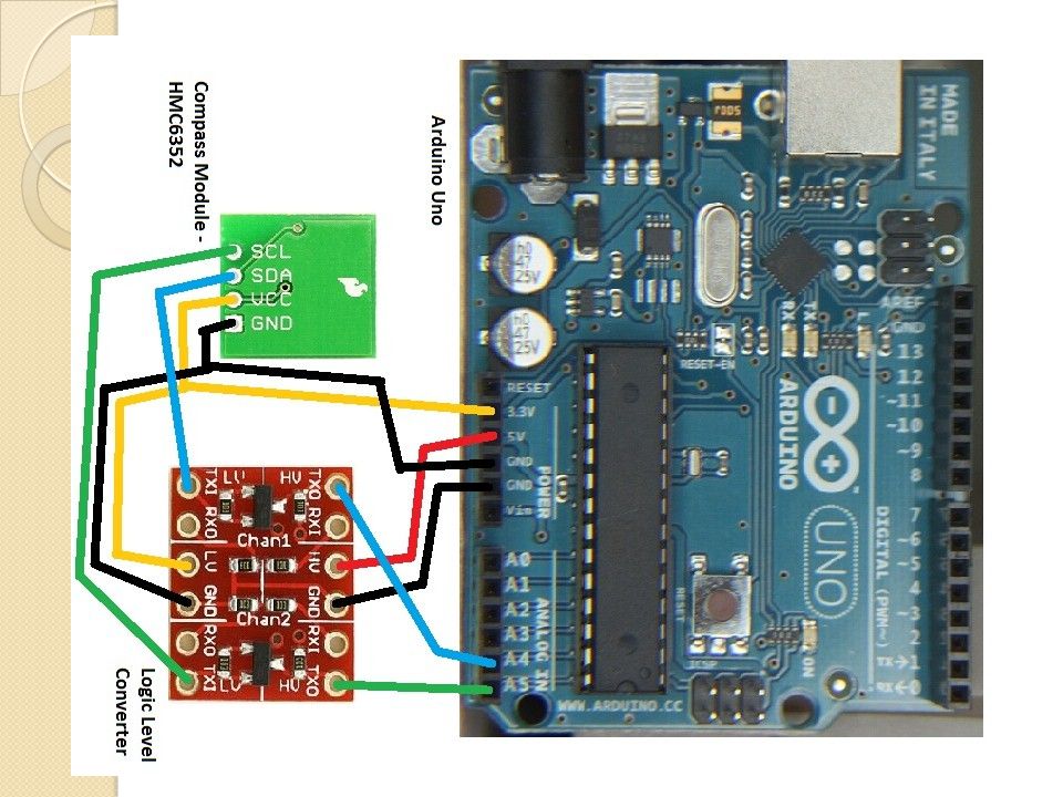
16
Voltage Level Converter If you've ever tried to connect a 3.3V device to a 5V system, you know what a challenge it can be. The SparkFun logic level converter is a small device that safely steps down 5V signals to 3.3V and steps up 3.3V to 5V. Each level converter has the capability of converting 4 pins on the high side to 4 pins on the low side. Two inputs and two outputs are provided for each side.

18
Stimulus (IR Light Source) An IR LED, also known as IR transmitter, is a special purpose LED that transmits infrared rays in the range of 760 nm wavelength. Such LEDs are usually made of gallium arsenide or aluminum gallium arsenide.

19
L293D H-Bridge The L293D is a H Bridge type IC and can control DC motors up to 36V. it's possible to drive 2 motors with a single L293D, however the power supply has to be strong enough to provide enough current.

20
L293D H-Bridge

21
4n25 optocoupler An optocouplter or optoisolator is a cool little device that allows you to completely separate sections of an electrical circuit. From what I understand, the MIDI protocol requires the use of optocouplers in all devices. I want to use an optocoupler for separating a circuit powered by USB (5V) from one powered by a 7.2V RC Car battery. The idea behind this is that I want to protect the USB based circuit(and my computer) from the large amperages, inductance, higher voltages and other things going on in the RC Car side of the circuit, but still want to be able to control it using a USB device.
 from one powered by a 7.2V RC Car battery. The idea behind this is that I want to protect the USB based circuit(and my computer) from the large amperages, inductance, higher voltages and other things going on in the RC Car side of the circuit, but still want to be able to control it using a USB device..")
22
microcontroller

23
Software System Arduino IDE 1.5.2

24
Robot #2 It’s the part that holds the IR-LED, and escape from the first robot.

25
Remote We use it to control the movement of the car. Component : - PIC 18F4620. - 4 push buttons & 4 resistors. - XBee module “Transmitter”.

26
How does it work ! The PIC read the buttons, it detect what is pressed then send controlling command serially to the car via XBee module.

27
Moving car It will receive command from the remote. Component: - PIC 18F4620. - Mechanical body. - Motor controller “L293D”. - XBee module “Receiver”.

28
How Does It Work! The PIC read serial data from XBee, process what is received and control L293D which control movement of the motor.

29
What does we do in PIC C code? In remote : btn = input_a(); btn = btn & 0x0F ; // 0000 1111 if(btn == 0x02) //0000 0010 { printf("F"); //Forward delay_ms(200); }
; btn = btn & 0x0F ; // if(btn == 0x02) // { printf( F ); //Forward delay_ms(200); }.")
30
What does we do in PIC C code? In car : if( kbhit()) //chick if any think is received { c = getchar(); delay_ms(100); if(c=='F') { output_d(0x02);//0000 0010 }
) //chick if any think is received { c = getchar(); delay_ms(100); if(c== F ) { output_d(0x02);// }.")
31
X-Bee Module Wireless connection between end point. The speed is 250 Kbps but with noise it gives speed upto 25 Kbps. It transmit and receive data serially. Once it configured you can use it easely.

32
Problems Wiimote Camera!!! XBEE Wireless Component L293D H-bridge Noise !!

33
DEMO

Similar presentations


 By: Ashwaq Alkailany Reema Abubaker Supervised by: Dr. Luia Malhis.>")


 Manoj Bhambwani Tameka Thomas.>")


 James Cover (CE) Alexander Eschbach (EE) Jason Hang (ME) Ashley Trode (EE) Guide:>")


>")