Download presentation
Presentation is loading. Please wait.

1
6 UAA – ACCT 316 – Fall 2003 Accounting Information Systems
Dr. Fred Barbee Chapter 1

2
Documentation Techniques
Used by 62.5% of IT Professionals Data Flow Diagrams Document Flowcharts System Flowcharts Program Flowcharts Used by 97.6% of IT Professionals

3
Documentation Techniques
Data Flow Diagrams Document Flowcharts System Flowcharts Program Flowcharts More than 92% use both DFDs and flowcharts.

4
Typical Information System
Computer-based; Has a number of terminals connected to it via telecommunications links; Is used by dozens of people within and outside the organization;

5
Typical Information System
Has hundreds of programs that perform functions for virtually every department in the organization. Processes thousands of transactions and hundreds of requests for management information.

6
For such a system . . . We need “pictures” rather than a narrative description to “see” and analyze all the inputs and outputs.

7
Using Document Flowcharts
Who? Where? What?

8
Documentation Techniques
. . . are tools used in analyzing, designing, and documenting system and subsystem relationships . . .

9
Documentation Techniques
They are largely graphical in nature; Are essential to both internal and external auditors; and Are indispensable in the development of information systems.

10
Auditors 7

11
The Interim Audit . . . Objective is to establish the degree to which the organization’s internal structure can be relied upon. Usually requires some form of compliance testing.

12
Compliance Testing . . . The purpose of compliance testing is:
To confirm the existence, Assess the effectiveness, and Check the continuity of operations of the internal controls on which reliance is to be placed.

13
Compliance Testing . . . Compliance testing requires an understanding of the controls that are to be tested. In other words, you can’t test something you don’t understand.

14
Internal Control Structure
In evaluating internal controls auditors are concerned with the flow of processing and distribution of documents within an application system.

15
Systems Development 7

16
Systems Development . . . Consists of three phases:
Systems analysis; Systems design; and Systems implementation Each of these phases makes use of documentation techniques.

17
Management 7

18
Management As Users . . . Scheduling work;
Development of an internal control system; Reviewing the flow of work through the organization.

19
Other Users 7

20
You! Prepare Evaluate Read 7

21
Other Users . . . Training Description
Used to explain systems and to train personnel Description Used by auditors and others to understand complex systems; and To evaluate the systems internal controls.

22
Classification . . . Documentation is classified according to the level of the accounting system to which it relates.

23
Typical System Documentation
System narrative descriptions Block diagrams Document flowcharts Data flow diagrams

24
Overall System Documentation
System Flowcharts Program Flowcharts; and Decision Flowcharts

25
In Terms of Level of Detail
Narrative descriptions are the most general overview and correspondingly show the fewest details. In Terms of Level of Detail System flowcharts provide less of an overview, but include the most detail in this class of documentation.

26
Narrative Descriptions
A written step-by-step explanation of system components and interactions. The highest and broadest form of documentation at the overall system level.

27
Narrative Descriptions
It represents the basic source of information regarding the system goals and objectives. Makes it possible to quickly understand the system without being involved with details.

28
Narrative Descriptions
A description of the reasons for building the system. Background Objectives Scope of system

29
Block Diagrams Block diagrams provide a graphic overview of a system.
Commonly used to provide an overview of an accounting system in terms of its major components and subsystems

30
Block Diagrams They help people understand a system without getting bogged down in details. Two types: Horizontal Block Diagram; and Hierarchical Block Diagram

31
Horizontal Block Diagrams
Blocks represent the various subsystems; While connecting lines represent the information flows among them.

32
Request for Goods and Services
Purchasing Cycle Request for Goods and Services Purchase Requisition Purchasing Purchase Order Receiving Report Receiving Document Process $ Cash Disb. Voucher Disb. Approval

33
Horizontal Block Diagram
Vendors and Employees Customer Customer Customer Bank Horizontal Block Diagram

34
Hierarchical Block Diagrams
Show the analysis of a system into successive levels of component subsystems. Connecting lines represent interlevel associations (parent-child relationships).
.")
35
Hierarchical Block Diagram of
The Revenue Cycle

36
Data Flow Diagrams Bridge the gap between
Narrow documentation types . . . System Flow Charts Broad documentation types . . . System Narratives Block Diagrams Document Flow charts

37
Data Flow Diagrams Provide . . .
More detailed representation of an accounting system than block diagrams Fewer technical details than system flowcharts.

38
Symbols For Data Flow Diagrams
Figure 6-1 (p. 158) 69
 69.")
39
Data Flow Diagram Symbols
Name Explanation Data sources and destinations The people and organizations that send data to and receive data from the system. Data Flows The flow of the data into or out of a process is represented by curved or straight lines with arrows.

40
Data Flow Diagram Symbols
Name Explanation Transformation Process The process that transforms data from inputs to outputs. Also known as “bubbles.” Data Stores The storage of data is represented by two horizontal lines.

41
Data Flow Diagrams The DFD should consist solely of DFD symbols;
Each symbol in the DFD, including each pointed flowline, should be labeled;

42
Data Flow Diagrams All names must be meaningful to the end-user.
All symbols must have an individual name. Diagrams are always named at the top or bottom. The name should identify the level and the system it represents.

43
Figure 6-2 Basic Data Flow Diagram Elements
30

44
Examples: Customer, Employees, Bank, etc.
AKA “Entity,” or “terminator.” Named with descriptive nouns or noun clauses. Figure Basic Data Flow Diagram Elements Examples: Customer, Employees, Bank, etc. 30

45
Examples: Process Payment, Update Receivables, etc.
Named with action verb or verb clause. The name must describe what action or transformation is occurring. Figure Basic Data Flow Diagram Elements Examples: Process Payment, Update Receivables, etc. 30

46
Examples: Accounts Receivable, General Ledger, etc.
Figure Basic Data Flow Diagram Elements Named with a noun clause that describes the contents of the data store. Should not include the word “data.” 30

47
Examples: Time Cards; Employee Data, etc.
AKA “Entity,” or “terminator.” Named with descriptive nouns or noun clauses. Named with a noun clause that describes the data carrier and how it is implemented. Figure Basic Data Flow Diagram Elements Examples: Time Cards; Employee Data, etc. 30

48
Figure 6-3 Data Flow Diagram of Customer Payment process
30

49
DFDs – Some Do’s and Don’ts
First – the Do’s 66

50
DFDs – Some Do’s and Don’ts
All data flows must begin at a process, end at a process, or both. This is absolute because data flows either initiate or result from a process.

51
DFDs – Some Do’s and Don’ts
Data stores cannot communicate with entities This would be the same as someone being able to enter an order into your database without checking it for accuracy or to see if the items were available.

52
DFDs – Some Do’s and Don’ts
Entities cannot communicate with other entities. While this may be beneficial, it is not of interest to the current system. If an entity communicates with another entity, the data flow does not have to go through the current system. This makes this particular data flow irrelevant to the current system.

53
DFDs – Some Do’s and Don’ts
Data stores cannot communicate with other data stores. This would be the same as something being placed in your inbox and you taking the item and placing it into someone else’s inbox without reading it. This probably does happen but that is not the way it should work. In fact, the system is not working, it is merely shuffling papers.

54
DFDs – Some Do’s and Don’ts
Processes can communicate with other processes.

55
DFDs – Some Do’s and Don’ts
All processes must have an incoming and outgoing data flow.

56
DFDs – Some Do’s and Don’ts
All entities must be introduced at the context level. This allows the boundaries of the system to be defined and the net inputs and outputs (data flows) to the system to be displayed.
 to the system to be displayed.")
57
DFDs – Some Do’s and Don’ts
Only entities and data store symbols may be duplicated. This is necessary in order to correctly construct the diagrams and to comply with the major don’t – Data flows cannot cross. This eliminates any confusion on the user’s part. If data flows were allowed to cross, it makes it difficult to determine which way the flow is to go.

58
DFDs – Some Do’s and Don’ts
Do not cross data flows. This is to eliminate any confusion on the user’s part. If data flows were allowed to cross, it makes it difficult to determine which way the flow is to go.

59
DFDs – Some Do’s and Don’ts
Do not use double-ended arrow to represent data flows. You should separate them into two data flows. Again, it is easier on the user.

60
DFDs – Some Do’s and Don’ts
Do not use diverging arrow to represent data flows Make it into two separate data flows. Also, the opposite is true. You cannot use a converging arrow to represent data flows. Separate them. Remember the user. OK

61
DFDs – Some Do’s and Don’ts
Data stores do not appear on the context level diagram. On the context level there is only one process that represents the system. One of the requirements of a data store is that it is in the system. Thus, the system is the only thing reflected on the context level and not any internal detail. If data stores are on the context level, it would put them outside of the system.

62
Data Flow Diagrams Some Helpful Hints 66

63
DFDs Some Helpful Hints
Place entities on the outer edge of the paper. Place the processes toward the center Place data stores around the processes.

64
DFDs Some Helpful Hints
May need to move location of entities and data stores from level to level. Duplicate entities and data stores as needed to make drawing easier.

65
Data Flow Diagrams are Constructed in Levels
66

66
Data Flow Diagrams are constructed in levels.
The first or upper most level is referred to as the context level. The next is called level 0, the next level 1, and so on until level “n”, where “n” is some integer. Figure Context Diagram for S&S Payroll Processing 30

67
This is the first level on which data stores appear.
The level 0 DFD is created by exploding the context level into its main functions or divisions. Everything that is on the context level is transferred to level 0. The new processes are added with any new data flows and data stores. This is the first level on which data stores appear. Figure DFD for S&S Payroll Processing 30

68
Figure 6-7 DFD for Process 2.0 in S&S Payroll Processing
30

69
Let’s pause here and do some data flow diagrams. First P6-9 (p. 180)
")
70
Ashton Fleming has worked furiously for the past month trying to completely document the major business information flows at S&S. Upon completing his personal interviews with cash receipts clerks, Ashton asks you to develop a comprehensive DFD for the cash receipts system. Ashton’s narrative of the system follows:

71
Customer payments include cash received at the time of purchase and account payments received in the mail. At day’s end, the treasurer endorses all checks and prepares a deposit slip for the checks and the cash. A clerk then deposits the checks, cash, and deposit slip at the local bank each day.

72
When checks are received as payment for accounts due, a remittance slip is included with the payment. The remittance slips are used to update the accounts receivable file at the end of the day. The remittance slips are stored in a file drawer by date.

73
Every week, a cash receipts report and an aged trial balance are generated from the data in the accounts receivable ledger. The cash receipts report is sent to Scott and Susan. A copy of the aged trial balance by customer account is sent to the Credit and Collections Department.

74
Required Develop a context diagram and a DFD for the cash receipts system at S&S.

75
Context Level Diagram Shows the boundary of the system;
Shows the name of the system; Shows net data flows to and from the system; and Identifys all entities.

76
Context Level Diagram On the context level, the system is represented by a single process symbol with the number 0. The name of the system is used for the process.

77
OK Let’s Identify . . . Data sources and destinations (terminators); Transformation processes; Data stores; and Data flows

78
Customer payments include cash received at the time of purchase as well as accounts payments received in the mail. At the end of the day, all checks are endorsed by the treasurer and a deposit slip is prepared for the checks and the cash. The checks, cash, and deposit slip are then deposited daily at the local bank by a clerk.

79
When checks are received as payment for accounts due, a remittance slip is included with the payment. The remittance slips are used to update the accounts receivable file at the end of the day. The remittance slips are stored in a file drawer by date.

80
Every week, a cash receipts report and an aged trial balance are generated from the data in the accounts receivable ledger. The cash receipts report is sent to Scott and Susan. A copy of the aged trial balance by customer account is sent to the Credit and Collections Department.

81
Remittances on Account
Context Diagram of the Cash Receipts System at S&S Bank Deposit Payments at Sale Cash Receipts System Customers Management Cash Receipts Report Remittances on Account Credit and Collection Aged Trial Balance

82
OK Let’s Identify . . . Data sources and destinations (terminators); Transformation processes; Data stores; and Data flows

83
Customer payments include cash received at the time of purchase as well as accounts payments received in the mail. At the end of the day, all checks are endorsed by the treasurer and a deposit slip is prepared for the checks and the cash. The checks, cash, and deposit slip are then deposited daily at the local bank by a clerk.

84
Customer payments include cash received at the time of purchase as well as accounts payments received in the mail. At the end of the day, all checks are endorsed by the treasurer and a deposit slip is prepared for the checks and the cash. The checks, cash, and deposit slip are then deposited daily at the local bank by a clerk. Process Checks

85
When checks are received as payment for accounts due, a remittance slip is included with the payment. The remittance slips are used to update the accounts receivable file at the end of the day. The remittance slips are stored in a file drawer by date.

86
Update Accounts Receivable
When checks are received as payment for accounts due, a remittance slip is included with the payment. The remittance slips are used to update the accounts receivable file at the end of the day. The remittance slips are stored in a file drawer by date. Update Accounts Receivable

87
Every week, a cash receipts report and an aged trial balance are generated from the data in the accounts receivable ledger. The cash receipts report is sent to Scott and Susan. A copy of the aged trial balance by customer account is sent to the Credit and Collections Department.

88
Every week, a cash receipts report and an aged trial balance are generated from the data in the accounts receivable ledger. The cash receipts report is sent to Scott and Susan. A copy of the aged trial balance by customer account is sent to the Credit and Collections Department. Prepare Reports

89
What are the Processes? Process checks (1.0)
Update Customer Accounts (2.0) Prepare Reports (3.0)
 Prepare Reports (3.0)")
91
Wow! That was fun! Now, let’s see if you can do it!
Try P (p. 179)
")
92
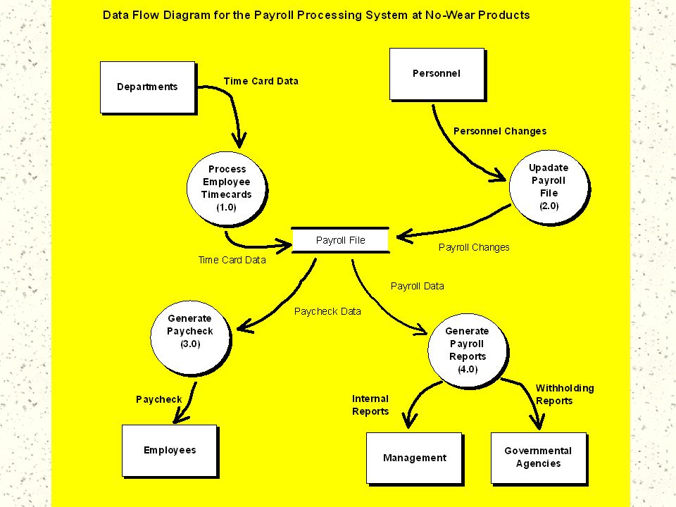
As the internal auditor for No-Wear Products of Hibbing, MN, you have been asked by your supervisor to document the company’s current payroll processing system. Based on your documentation, No-Wear hopes to develop a plan for revising the current IS to eliminate unnecessary delays in paycheck processing.

93
Your best explanation of the system came from an interview with the head payroll clerk.
The payroll processing system at No-Wear Products is fairly simple. Time data are recorded in each department using time cards and clocks.

94
It is annoying, however, when people forget to punch out at night and we have to record their time information by hand. At the end of the period, our payroll clerks enter the time card data into a payroll file for processing. Our clerks are pretty good – though I’ve had to make my share of corrections when they mess up the data entry.

95
Before the payroll file is processed for the current period, human resources sends us data on personnel changes, such as increases in pay rates and new employees. Our clerks enter this information into the payroll file so it is available for processing. Usually, when mistakes get back to us, it’s because human resources is recording the wrong pay rate or an employee has left and the department forgets to remove the record.

96
The data are then processed and individual employee paychecks are generated. Several important reports are also generated for management – though I don’t know exactly what they do with them. In addition, the government requires regular federal and state withholding reports for tax purposes. Currently, the system generates these reports automatically, which is nice.

97
Required Prepare a context diagram for the current payroll processing system at No-Wear Products. Develop a DFD to document the payroll processing system at no- Wear Products.

100
Wow! That was fun! Now, let’s see if you can do it!
Try P (p. 181)
")
101
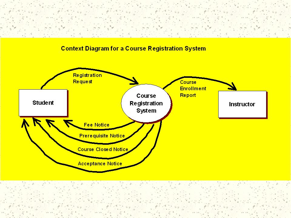
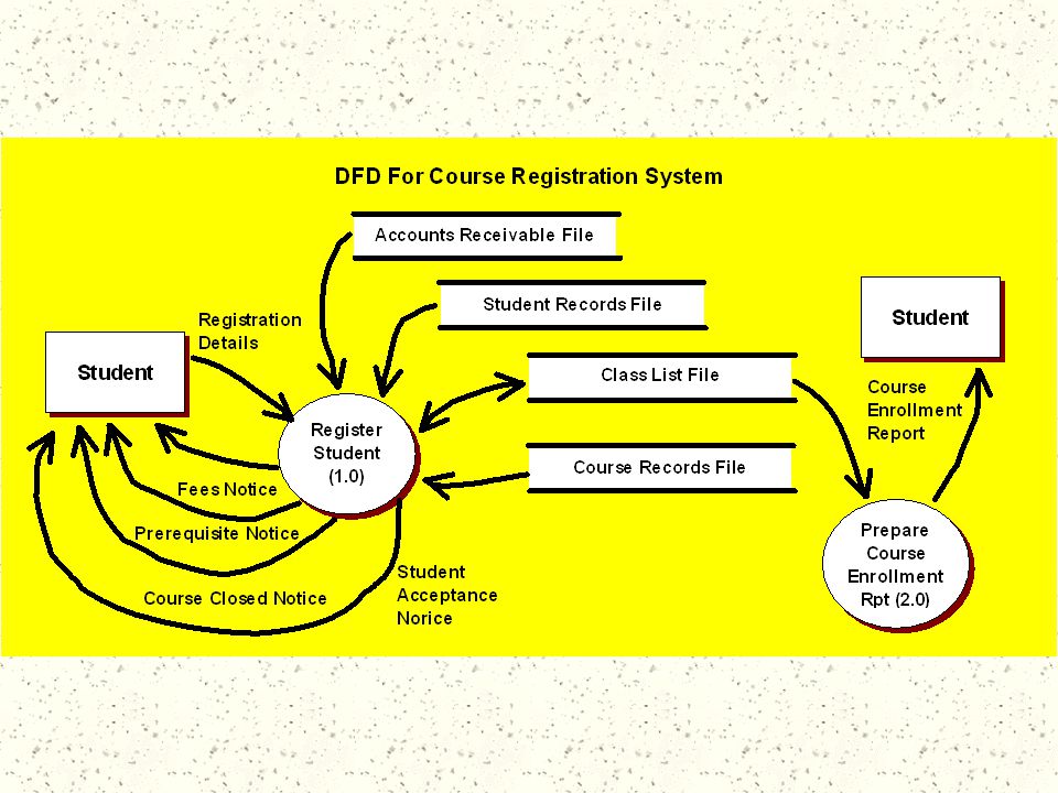
The local community college requires that each student complete a registration request form and mail or deliver it to the registrar’s office. A clerk enters the request into the system. First, the system checks accounts receivable subsystem to ensure that no fees are owed from the previous quarter. Next, for each course, the system checks the student transcript to ensure that he or she has completed the course prerequisites. Then the system checks class position availability and adds the students SSN to the class list.

102
The report back to the student shows the result of registration processing: If the student owes fees, a bill is sent and the registration is rejected. If prerequisites for a course are not fulfilled, the student is notified and that course is not registered. If the class is full, the student request is annotated with “course closed.”

103
If a student is accepted into a class, then the day, time, and room are printed next to the course number. Student fees and total tuition are computed and printed on the form. Student fee information is interfaced to the accounts receivable subsystem. Course enrollment reports are prepared for the instructors.

104
Required Prepare a context diagram and at least two levels of logical DFDs for this operation.

Similar presentations