Download presentation
Presentation is loading. Please wait.

1
Cams are used to convert rotary motion into reciprocating motion
Cam - A mechanical device used to transmit motion to a follower by direct contact. Cam – driver; Follower - driven In a cam - follower pair, the cam normally rotates while the follower may translate or oscillate. Cams are used to convert rotary motion into reciprocating motion

2
Three elements of the cam

3
In IC engines to operate the inlet and exhaust valves

4
CAMS Follower motions having almost any desired characteristics are not difficult to design. By desired characteristics are typically meant the following: Displacement – the height or distance through which the follower is moved for one revolution of the cam; Velocity – the speed with which the cam moves the follower; Acceleration – the rate of change of velocity of the follower Jerk – the rate of change of acceleration.

8
CLASSIFICATION OF CAMS
(i) Based on the physical shape (a) Disk or plate cams
 Based on the physical shape (a) Disk or plate cams")
9
(b) Cylindrical cam
 Cylindrical cam")
10
Translation Cam (Wedge Cam)
Not very commonly used. The cam moves over and back, reciprocating motion, which drives the follower vertically.

11
CLASSIFICATION OF FOLLOWES
Based on surface in contact (a) Knife edge follower (b) Roller follower (c) Flat faced follower (d) Spherical follower
 Knife edge follower. (b) Roller follower. (c) Flat faced follower. (d) Spherical follower.")
12
KNIFE OR POINT EDGE FOLLOWER
FLAT FACED FOLLOWER ROLLER FOLLOWER

13
(ii) Based on type of motion
Oscillating follower Translating follower

14
(iii) Based on line of action
Radial (in line) follower
 follower.")
15
(b) Off-set follower
 Off-set follower")
16
1.2 Classification of CAM Mechanism
Based on modes of Input / Output motion 1 Rotating cam –Translating follower 2 Rotating cam – Oscillating follower 3 Translating cam – Translating follower

17
Classification of followers
According to the shape of follower Knife edge follower Roller follower Flat faced follower Spherical faced follower

18
Classification of cams
Radial or disc cam In radial cams, the follower reciprocates or oscillates in a direction perpendicular to the cam axis b) Cylindrical cam In cylindrical cams, the follower reciprocates or oscillates in a direction parallel to the cams axis. c) End cam It is also similar to cylindrical cams, but the follower makes contact at periphery of the cam.
 Cylindrical cam. In cylindrical cams, the follower reciprocates or oscillates in a direction parallel to the cams axis. c) End cam. It is also similar to cylindrical cams, but the follower makes contact at periphery of the cam.")
19
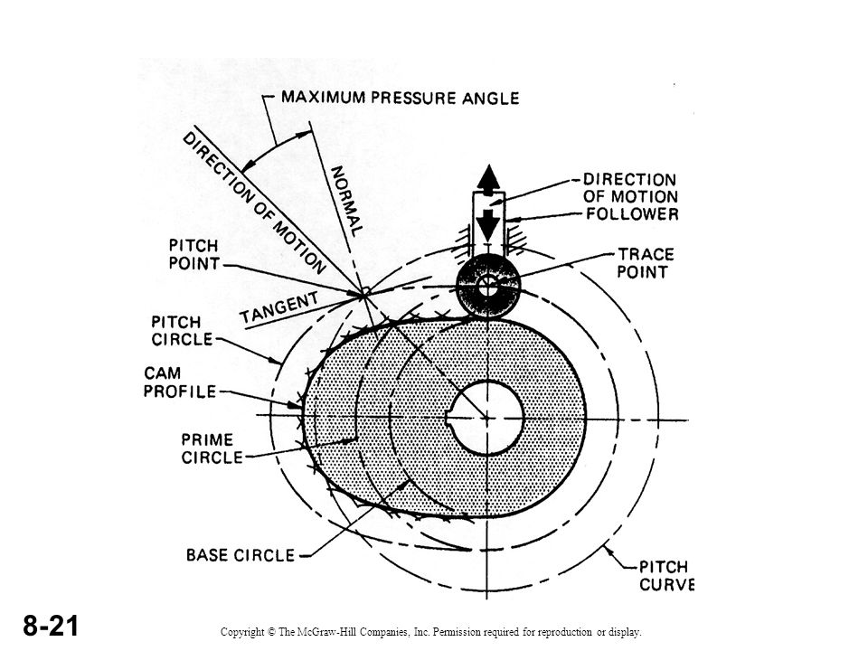
Cam nomenclature

20
. CAM Nomenclature

22
Cam profile : The outer surface of the disc cam.
Base circle: The smallest circle drawn on the cam profile. Trace point: The center line of the follower roller or its equivalent.

23
Pitch curve: The locus of successive positions of the trace point as cam displacement takes place.
Prime circle: The smallest circle drawn on the pitch curve from the cam center. Pressure angle: the angle between the normal to the pitch curve and the instantaneous direction of motion of the follower.

24
Pitch circle: The circle which passes through the pitch point.
Cam terms Pitch point: The position of the pitch curve where the pressure angle is maximum. Pitch circle: The circle which passes through the pitch point.

26
Pressure angle = α = 0 (fig. A)
= 450 (fig.B) Angle of outstroke = 800 Angle of dwell 1 = 200 Angle of return stroke = 800 Angle of dwell 2 = 1800
 Angle of outstroke = 800. Angle of dwell 1 = 200. Angle of return stroke = 800. Angle of dwell 2 =")
27
Influence of off set on pressure angle

28
PROFILE SHAPES OF SOME CAMS
PEAR-SHAPED CAMS: These type cams are often used for controlling valves. For example, they are used on motor car camshafts to operate the engine valves. A follower controlled by a pear-shaped cam remains motionless for about half a revolution of the cam. During the time that the follower is stationary, the cam is in a dwell period. During the other half revolution of the cam, the follower rises and then falls. As the pear-shaped cam is symmetrical, the rise motion is the same as the fall motion.

29
Edge cams It must be appreciated that this type of cam, where the follower is in contact with the edge of the cam disc, is only capable of imparting positive motion to its follower in one direction, that is, during the rise portion of the cam movement. During the fall portion of the cam movement the follower must be maintained in contact with the cam either by the mass of the follower and its mechanism or, more usually, by a spring. Both methods have their advantages.

30
Box cams A groove can be milled in the face of cam discs. As the cam rotates, a follower located in the groove has its motion guided by the groove. This type of cam is called a box cam.

31
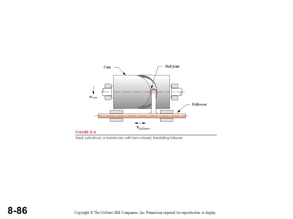
Cylindrical cams: Cylindrical cams are used when motion has to be transmitted parallel to the axis of rotation of the cam. The cylindrical or barrel cam consists of a rotating cylinder with a helical (screw shaped) groove in its curved surface. A follower with a tapered roller end is located in the groove. As the cylinder turns, the follower moves in a straight line parallel to the axis of the rotation barrel cam. This type of cam is often used to guide thread on sewing machines, looms and fabric making machines.
 groove in its curved surface. A follower with a tapered roller end is located in the groove. As the cylinder turns, the follower moves in a straight line parallel to the axis of the rotation barrel cam. This type of cam is often used to guide thread on sewing machines, looms and fabric making machines.")
32
CIRCULAR CAMS: These cams are sometimes called eccentric cams
CIRCULAR CAMS: These cams are sometimes called eccentric cams. The cam profile is a circle. The center of rotation of the cam is often from the geometric center of the circle. The circular cam produces a smooth form of motion called a simple harmonic motion. These cams are often used to produce motion in pumps. Circular cams are often used to operate steam engine valves. As the cam is symmetrical, the rise and fall motions are the same.

33
HEART SHAPED CAMS: This cam causes the follower to move with a uniform velocity. Heart-shaped cams are essential when the follower motion needs to be uniform or steady as, for example, in the mechanism that winds thread evenly on the bobbin of a sewing machine. A heart-shaped cam can be used for winding wire evenly on the former of a solenoid.

34
Example of cam action

35
Cam-Valve

36
Types of follower motion
Follower motion with, Uniform velocity Modified uniform velocity Uniform acceleration and deceleration Simple harmonic motion Cycloidal motion

37
DISPLACEMENT DIAGRAMS
The input motion θ (t) is derived from the angular velocity of the shaft, ω. The output displacement of the follower Y(t) consists of rises, dwells and falls. What is typically required is to design a cam to provide an output motion Y ( t ) for a given angular motion input. The diagram below shows a typical displacement diagram for a disc cam with one rise, one fall and two dwells occurring within a cam rotation of 360 degrees. A cam may have multiple rises and falls, no dwells, or whatever configuration is necessary for the desired follower motion.
 is derived from the angular velocity of the shaft, ω. The output displacement of the follower Y(t) consists of rises, dwells and falls. What is typically required is to design a cam to provide an output motion Y ( t ) for a given angular motion input. The diagram below shows a typical displacement diagram for a disc cam with one rise, one fall and two dwells occurring within a cam rotation of 360 degrees. A cam may have multiple rises and falls, no dwells, or whatever configuration is necessary for the desired follower motion.")
38
As the cam rotates the follower moves upward and downward.
Motion of the follower As the cam rotates the follower moves upward and downward. The upward movement of follower is called rise (Outstroke) The downward movement is called fall (Returnstroke). When the follower is not moving upward and downward even when the cam rotates, it is called dwell.
 The downward movement is called fall (Returnstroke). When the follower is not moving upward and downward even when the cam rotates, it is called dwell.")
39
Displacement diagrams
Displacement is the distance that a follower moves during one complete revolution (or cycle) of the cam while the follower is in contact with the cam. A displacement diagram is a graph of flat-pattern drawing of the travel (displacement) of the follower on the cam. A period is a part of the cam cycle and it includes the following: Rise – the upward motion of the follower caused by cam motion. Fall – the downward motion of the follower caused by cam motion. Dwell – the stationary position of the follower caused by cam motion. Spostamento è la distanza che un seguace si muove nel corso di un giro completo (o ciclo) della camma, mentre il seguace è in contatto con la camma. Un diagramma spostamento è un grafico di appartamento disegno modello del viaggio (spostamento) del seguace sulla camma. Un periodo è una parte del ciclo di Cam e comprende le seguenti: Rise - il movimento verso l'alto del seguace causato dal movimento della camma. Autunno - il movimento al ribasso del seguace causato dal movimento della camma. Dwell - la posizione di fermo del seguace causato dal movimento della camma.
 of the cam while the follower is in contact with the cam. A displacement diagram is a graph of flat-pattern drawing of the travel (displacement) of the follower on the cam. A period is a part of the cam cycle and it includes the following: Rise – the upward motion of the follower caused by cam motion. Fall – the downward motion of the follower caused by cam motion. Dwell – the stationary position of the follower caused by cam motion. Spostamento è la distanza che un seguace si muove nel corso di un giro completo (o ciclo) della camma, mentre il seguace è in contatto con la camma. Un diagramma spostamento è un grafico di appartamento disegno modello del viaggio (spostamento) del seguace sulla camma. Un periodo è una parte del ciclo di Cam e comprende le seguenti: Rise - il movimento verso l alto del seguace causato dal movimento della camma. Autunno - il movimento al ribasso del seguace causato dal movimento della camma. Dwell - la posizione di fermo del seguace causato dal movimento della camma.")
42
When the cam turns through one motion cycle, the follower executes a series of events consisting of rises, dwells, and returns. Rise is the motion of the follower away from the cam center; dwell is the motion during which the follower is at rest; and return is the motion of the follower toward the cam center. Quando la camma trasforma attraverso un ciclo di movimento, il seguace esegue una serie di eventi di aumenti consistenti, si sofferma, e restituisceAumento è il movimento del seguace di distanza dal centro a camme; abitare è il movimento durante il quale l'inseguitore è a riposo, e ritorno è il movimento del seguace verso il centro della camma There are three different types of follower motion in standard use, which are shown below.

43
Uniform (constant) velocity:
Cam motions: Uniform (constant) velocity: Since the velocity is constant, the displacement diagram will be a straight line with constant slope.
 velocity: Since the velocity is constant, the displacement diagram will be a straight line with constant slope.")
44
Normally, uniform motion is modified by arcs drawn at the start and end of the period. The arc radius is normally half or quarter the follower displacement. Step 1. Draw the base circle line using any convenient distance Step 2. Divide it into 12 equal divisions. Step 3. Draw the follower displacement height line vertical to the base circle line. Create a rectangle, using the base circle line and the follower displacement line as the width and height, respectively.

45
Step 4. Draw a straight line from 00 to the top of 1800 and then down again to This line represents the displacement diagram for uniform motion. Step 5. Modify the straight displacement line by drawing arcs at 0, 180 and 360 degrees. The arc radius is equal to one-fourth to one-half the follower displacement.

46
Step 6. Darken the modified line.

47
a) Follower motion with Uniform velocity
 Follower motion with Uniform velocity")
48
(b) Follower motion with modified uniform velocity
 Follower motion with modified uniform velocity")
49
(d) Simple Harmonic Motion
motion executed by point Pl, which is the projection of point P on the vertical diameter

50
Simple Harmonic Motion
Displacement = ; Velocity = ; Acceleration = ; Simple Harmonic Motion

51
Simple harmonic motion.
The displacement diagram is a sine curve. Consideration shows that this type of cam will give the smoothest change of motion in the follower. Simple harmonic motion follower performance graph.

52
Simple Harmonic Motion

53
Step 1. Create a rectangle, using the base circle line and the follower displacement line as the width and height, respectively. Step 2. Draw a semi-circle at one end and divide it into 6 equal divisions. Step 3. Project the divisions from the semi-circle to get the points on the displacement diagram.

54
Step 4. Trace the points of the displacement diagram and darken the line.

55
Uniform acceleration and retardation.
This displacement curve is parabolic. It gives a uniform rate of acceleration from the start to the midpoint and a similar uniform rate of retardation from the midpoint to the end of the movement.

56
Step 1. Create a rectangle, using the base circle line and the follower displacement line as the width and height, respectively. Step 2. Proportionally divide the two halves of the follower displacement into ratios of 1, 4, 9. Step 3. Project the divisions to get the points on the displacement diagram.

57
Step 4. Trace the points of the displacement diagram and darken the line.

58
(c) Follower motion with uniform acceleration and retardation (UARM)
 Follower motion with uniform acceleration and retardation (UARM)")
59
Combination motion displacement diagram
The example shown next shows a displacement diagram imparting the following motions: Performance Data Upward stroke during 60° of cam rotation at constant velocity; Dwell for 30° of cam rotation; Upward stroke during 90° of cam rotation with simple harmonic motion; and Fall to it’s original position for the remainder of the cam’s revolution with uniform acceleration and deceleration. Step 1. Draw the base circle, divide it into 12 equal divisions and a follower displacement height.

60
Step 2. Mark the distances for the four different displacements.
Step 3. Construct the uniform motion displacement diagram (0 – 60°) Step 4. Construct a dwell displacement (60° – 90°) Step 5. Construct a simple harmonic motion displacement diagram (90° – 180°). In this case you will have to divide the base line into 15° sections.
 Step 4. Construct a dwell displacement (60° – 90°) Step 5. Construct a simple harmonic motion displacement diagram (90° – 180°). In this case you will have to divide the base line into 15° sections.")
61
Step 6. Construct a uniform acceleration and deceleration displacement diagram (180° – 360°)
")
62
Cam rotation directions
Drawing cam profiles. Now that we have seen the various types of cams and cam followers, we can now begin to draw a cam profile according to the given cam data. In order to draw a cam profile we must know how to draw the cam displacement diagram. You have already viewed these diagrams, so make sure you know how to draw each one before you try to draw the cam profile. Cam rotation directions Before you begin to draw a cam profile according to the given data, you must know what direction the cam is to rotate. If the cam is to rotate in a clockwise direction, then the outside diameter of the profile is numbered in an anti-clockwise direction, so If the cam is to rotate in an anti-clockwise direction, then the outside diameter of the profile is numbered in a clockwise direction.

63
Constant velocity Step 1. Draw the displacement diagram.
Step 2. Draw the centre lines of the camshaft and the highest and lowest positions of the follower. Step 3. Project lines from points 1 – 12 on the displacement diagram to the stroke position of the follower.

64
Step 4. Inscribe a circle from the centre of the cam shaft to the highest point the follower will travel. Step 5. Divide this circle into 12 equal divisions.

65
Step 6. With a compass and the centre of the camshaft as centre, inscribe arcs from the stroke position to give you the profile of the cam. Step 7. Darken the cam profile.

66
Uniform velocity with a knife-edge follower animation
Cam data In-line knife edge follower, 50 mm minimum diameter, 40 mm lift (rise) with uniform velocity, 0 degrees to 90 degrees bottom dwell, 90 degrees to 180 degrees rise, 180 degrees to 270 degrees top dwell, 270 degrees to 360 fall, clockwise rotation.
 with uniform velocity, 0 degrees to 90 degrees bottom dwell, 90 degrees to 180 degrees rise, 180 degrees to 270 degrees top dwell, 270 degrees to 360 fall, clockwise rotation.")
67
Simple harmonic motion
Step 1. Draw the displacement diagram. Step 2. Draw the centre lines of the camshaft and the highest and lowest positions of the follower . Step 3. Project lines from points 1 – 12 on the displacement diagram to the stroke position of the follower.

68
Step 4. Inscribe a circle from the centre of the cam shaft to the highest point the follower will travel. Step 5. Divide the circle into 12 equal divisions.

69
Step 6. With a compass and the centre of the cam shaft as centre, inscribe arcs to give you the position of the profile of the cam. Step 7. Darken the cam profile.

70
Simple harmonic motion with a roller follower animation Cam data In-line roller follower, diameter 12 mm, minimum cam diameter 50 mm, total rise 42 mm, both rise and fall have simple harmonic motion, 0 to 90 degrees bottom dwell, 90 to 180 degrees rise with simple harmonic motion, 180 to 270 degrees top dwell, 270 to 360 degrees fall with simple harmonic motion, because this is a symmetrical cam it can rotate in either direction.

71
Uniform acceleration and retardation with an incline flat face follower animation Cam data, In-line flat face follower, minimum cam diameter 50 mm, rise 36 mm through 180 degrees and a similar fall, both having U.A.R., this produces a symmetrical cam giving the required follower motion with either direction of rotation.

72
Combination Steps Follow the steps in constructing the simple harmonic motion. Step 6. Add more divisions to the constant velocity and simple harmonic sections.

73
Step 7. Construct the constant velocity and dwell sections of the cam profile.

74
Step 8. Construct the simple harmonic motion section of the cam profile.

75
Step 9. Construct the uniform acceleration and deceleration section of the cam profile.

76
1. Roller follower 2. Offset follower
The construction of the roller follower cam is similar to the knife edge follower. The difference is, with the roller follower you will look for the centre of the roller at the twelve different positions. You will get the cam profile by drawing a curve tangent to the twelve roller circles. The example shown next shows how this is done. 2. Offset follower An offset cam roller complicates the drawing of a cam profile because an offset circle must be drawn equal in radius to the amount of offset. The offset circle is divided into the same number of parts as the displacement diagram. A tangent line is then drawn from the points on the circumference of the offset circle to locate the centres for the roller along the pitch curve. The diagram below shows how to construct cam profile for an offset cam roller.

77
IN LINE ROLLER FOLLOWER
Step 1. Draw the displacement diagram as shown. Step 2. Position the camshaft axis to the side of the displacement diagram and a distance equal to the radius of the roller plus the least radius of the cam below it. Step 3. With centre the camshaft and radius the highest follower displacement inscribe a circle. Step 4. Divide this circle into the same number of divisions as the displacement diagram. Step 5. Project points 1 – 12 from the displacement diagram to the follower axis. Step 6. With centre the camshaft axis and radius to the points of division on the follower axis, describe arcs to intersect the radial line through the camshaft axis at points 1 – 12. Step 7. Draw roller circles at the points of intersection found in the previous step. Step 8. Draw a tangential curve to the roller circles to give the required cam profile.

78
OFFSET ROLLER FOLLOWER
Step 1. Draw the displacement diagram as shown. Step 2. Position the camshaft axis to the side of the displacement diagram and a distance equal to the radius of the roller plus the least radius of the cam below it. Step 3. With centre the camshaft and radius the highest follower displacement inscribe a circle. Step 4. Divide this circle into the same number of divisions as the displacement diagram. Step 5. Project points 1 – 12 from the displacement diagram to the follower axis. Step 6. Step 7. Draw roller circles at the points of intersection found in the previous step. Step 8. Draw a tangential curve to the roller circles to give the required cam profile.

79
Uniform velocity with offset roller follower animation
Cam data minimum cam diameter 50 mm, bottom dwell 0 to 60 degrees, rise 60 to 150 degrees, top dwell 150 to 210 degrees, fall 210 to 300 degrees 300 to 360 degrees bottom dwell, total lift 36 mm, uniform velocity, clockwise rotation, roller follower diameter 12 mm, offset 20 mm to the right of the cam centerline.

80
Uniform acceleration and retardation + uniform velocity, with a knife-edge follower animation
Cam data, In-line knife edge follower, minimum cam diameter 50 mm, rise 42 mm through 180 degrees with uniform acceleration and retardation, fall 42 mm through 180 degrees with uniform velocity, clockwise rotation.

Similar presentations


 or oscillatory motion to rotary motion (rarely) For high speed applications.>")


>")
>")
