Download presentation
Presentation is loading. Please wait.

1
MEEN 4110 – Mechanisms Design Fall - 2010 Lecture 09
CAM

2
Up on completion of this chapter, the student will be able to
Chapters Objectives Up on completion of this chapter, the student will be able to Understand how to design a CAM-FOLLOWER Systems.

3
Cam Follower

4
Cam A cam is a rotating or sliding piece in a mechanical linkage used especially in transforming rotary motion into linear motion or vice versa. It is often a part of a rotating wheel (eg. an eccentric wheel) or shaft (eg a cylinder with an irregular shape) that strikes a lever at one or more points on its circular path. The cam can be a simple tooth, as is used to deliver pulses of power to a steam hammer, for example, or an eccentric disc or other shape that produces a smooth reciprocating (back and forth) motion in the follower which is a lever making contact with the cam. The reason the cam acts as a lever is because the hole is not directly in the centre, therefore moving the cam rather than just spinning. On the other hand, some cams are made with a hole exactly in the centre and their sides act as cams to move the levers touching them to move up and down or to go back and forth.
 or shaft (eg a cylinder with an irregular shape) that strikes a lever at one or more points on its circular path. The cam can be a simple tooth, as is used to deliver pulses of power to a steam hammer, for example, or an eccentric disc or other shape that produces a smooth reciprocating (back and forth) motion in the follower which is a lever making contact with the cam. The reason the cam acts as a lever is because the hole is not directly in the centre, therefore moving the cam rather than just spinning. On the other hand, some cams are made with a hole exactly in the centre and their sides act as cams to move the levers touching them to move up and down or to go back and forth.")
5
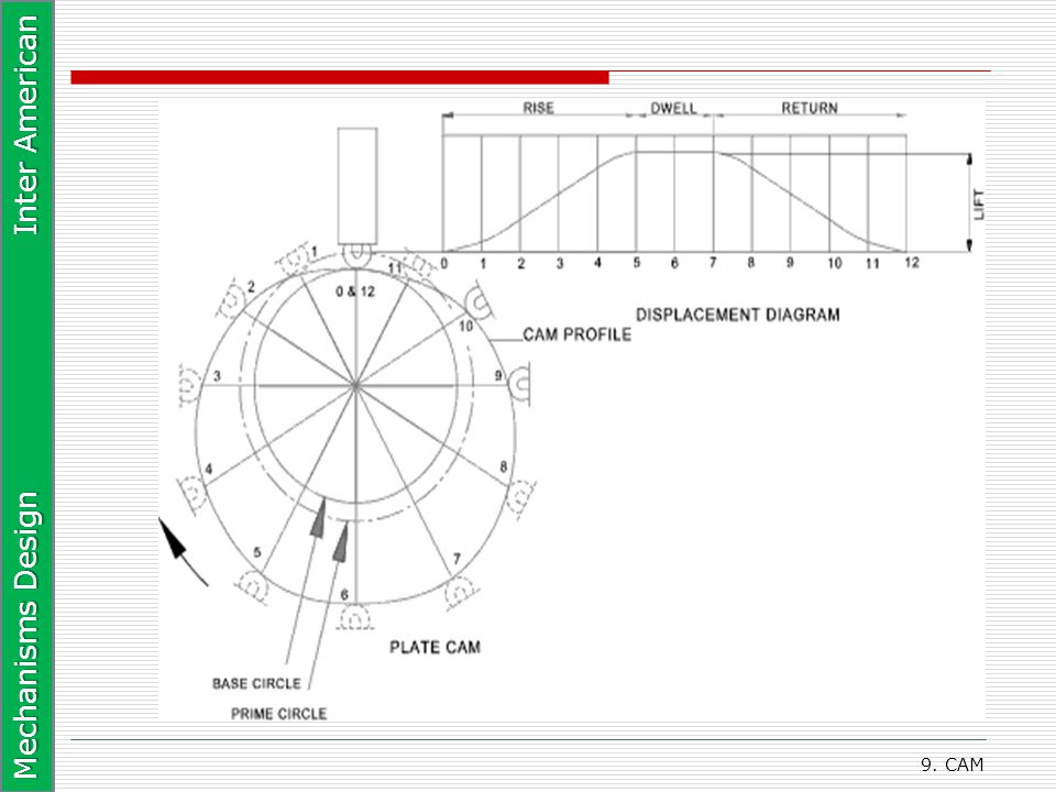
Design of Cam Systems The first stage in designing a cam system is the creation of a displacement diagram. A typical plate cam with an in-line roller follower is shown below with a displacement diagram. This figure shows the following characteristic features. The rise- This is when the follower is moving away from the cam centre. The slope reflects the follower velocity. The dwell- the is the period when the follower is stationary The return - This is when the follower moves back towards the cam centre The base circle on the cam is the smallest full diameter of the cam The prime circle is centered on the cam rotation centre with radius at the follower roller centre when the follower is on the base circle The cam profile is the shaped surface of the cam defining the follower motion

7
Cam Design

8
Types of Cams

9
Types of Joint Closers (cam/follower joint)
")
10
Follower Motion

11
Types of Followers

12
Obtaining the S Diagram

13
Unwrapping/Linearizing a Cam

14
Unwrapping/Linearizing a Cam

15
The S Diagram

16
Why S Diagram Cannot Have Negative Values
New

17
SVAJ Diagram

18
SVAJ Diagram

19
SVAJ Diagram

20
Type of Motion Constraints

21
Type of Motion Program RF = rise-fall RFD = rise-fall-dwell
RDFD = rise-dwell-fall-dwell

22
Double-Dwell Cam Design- Choosing SVAJ Functions

23
How Not Meet Cam Design Specifications (Linear Function)
")
24
SVAJ Diagram

25
SVAJ Diagram

26
Cycloidal Motion

27
Cycloidal Motion – SVAJ Diagram

28
a Diagram

29
v Diagram

30
s Diagram

31
Cycloidal Displacement Function

32
Polynomial Function

33
Polynomial Function

34
Polynomial Function

35
SVAJ Diagram

36
Polynomial Function

37
Polynomial Function

38
Polynomial Function

39
Polynomial Function

40
Double Dwell Cam Design

41
Double Dwell Cam Design

42
Double Dwell Cam Design

43
Double Dwell Cam Design

44
Double Dwell Cam Design

45
Single Dwell Cam Design

46
Single Dwell Cam Design

47
Single Dwell Cam Design

48
Single Dwell Cam Design

49
Single Dwell Cam Design

50
Single Dwell Cam Design

51
Homework6 www.bc.inter.edu/facultad/omeza

Similar presentations


 or oscillatory motion to rotary motion (rarely) For high speed applications.>")


