Download presentation
Presentation is loading. Please wait.

1
Tier 2 Environmental Performance Tools Environmental Release Assessment

2
Releases Releases include any spilling, leaking, pumping, pouring, emitting, emptying, discharging, injecting, escaping, leaching, dumping, or disposing (including the abandonment or discarding of containers and other closed receptacles) into the environment of any chemical or chemical mixture.
 into the environment of any chemical or chemical mixture.")
3
Release Assessment Release assessments are documents that contain information on release rates, frequencies, media of releases, and other information needed to characterize issues related to the releases.

4
Assessment Steps 1.Identify purpose and need for release assessment. 2.Obtain a process flowsheet. 3.Identify and list waste and emission streams. 4.Examine the flowsheet for additional waste and emission streams. 5.For each identified release point, determine the best available method for quantifying the release rate. 6.Determine data or information needed to use the quantification methods. 7.Collect data and information to fill gaps. 8.Quantify the chemical’s release rates and frequencies and the media to which releases occur. 9.Document the release assessment, including uncertainties.

5
Process Analysis A process flow diagram (with basic information such as M&E balance, unit operations, energy duties, equipment sizes and operating conditions) is the key tool to begin the analysis. The process output streams that are not usable or salable can be identified from PFD. There are other releases not identifiable from a PFD.

6
Releases Sources Not Identifiable in a Flowsheet Fugitive emissions Venting of equipment, e.g., breathing and displacement losses, etc. Periodic equipment cleaning Transport container residuals, e.g., from drums, totes, tank trucks, rail cars, barges, etc. Incomplete separation, e.g., distillation, gravity phase separation, filtration, etc.

7
Classification of Releases On-site releases –Air releases Primary emissions (They o ccur as the direct consequence of the production or use of a compound within an industrial process.) –Stack release (point sources) –Fugitive emission (non-point source) Secondary emissions (They occur indirectly as a result of the production or use of a specific compound) –Water releases –Underground injection releases –Releases to land Off-site releases: Wastes to other facilities for disposal, treatment, energy recovery, or recycling.
 –Stack release (point sources) –Fugitive emission (non-point source) Secondary emissions (They occur indirectly as a result of the production or use of a specific compound) –Water releases –Underground injection releases –Releases to land Off-site releases: Wastes to other facilities for disposal, treatment, energy recovery, or recycling.")
8
Stack Releases Stack releases occur through stacks, vents, ducts, pipes, or other confined air streams. They include the vent emissions from storage tanks and unit operations (e.g., feed or product storage vents, pressure relief vents on reactor, vents on distillation columns condensers, absorption and stripping column vents) and air releases from air pollution control equipment. They are easily identifiable and relatively few in number.
 and air releases from air pollution control equipment. They are easily identifiable and relatively few in number..")
9
Fugitive Air Emissions These releases include equipment leaks from valves, pump seals, flanges, compressors, sampling connections, open-ended lines, and air releases from building ventilation system, etc. They are not easily identifiable and relatively large in number.

10
Secondary Emissions These emission sources include 1.Utility consumption, 2.Evaporative losses from surface impoundments and spills, and 3.Industrial wastewater collection systems.

11
Water Releases These releases include process outfalls such as pipes and open trenches, releases from on-site wastewater treatment systems, and from storm- water runoff.

12
Underground Injection Releases Some chemicals are allowed to be injected into wells at a facility.

13
Releases to Land On-site landfills Land treatment/application farming: A disposal method in which waste-containing water is applied onto or incorporated into soil. Surface impoundment: It is a natural topographic depression, man-made excavation, or diked area formed primarily of earthen materials that is designed to hold an accumulation of liquid wastes or waste containing free liquid. Spills or leaks of chemicals to land

14
Tier 2 Environmental Performance Tools Release Quantification

15
Release Quantification Methods Directly measured release data (or indirectly measured data from material balance or stoichiometric ratios). Release data for surrogate chemical Modeled release estimates –Mathematically modeled –Rule-of-thumb estimates or those using engineering judgment.

16
Emission Factors Emission factors are commonly used to estimate releases to air. The most recent and comprehensive emission factor document from the US EPA is titled the Factor Information Retrieval (FIRE) System. They are included in the Air CHIEF CD-ROM available from the US EPA.
 System. They are included in the Air CHIEF CD-ROM available from the US EPA..")
17
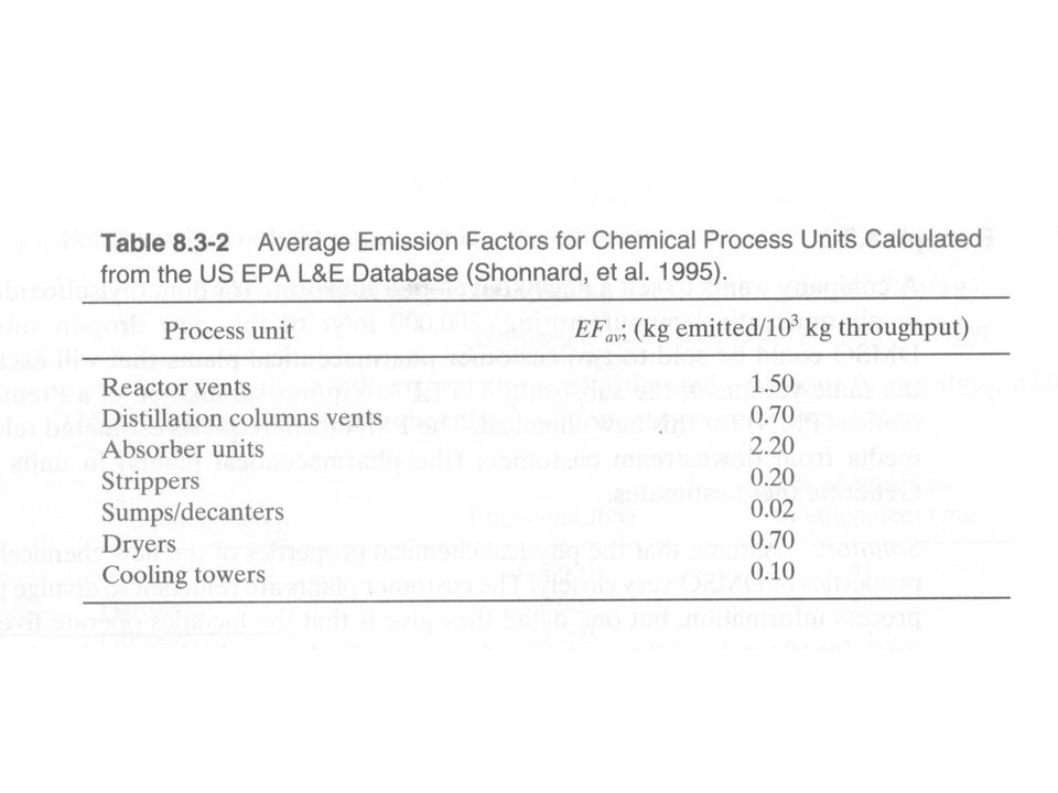
Emissions from Process Units and Fugitive Sources The rate of emission (E, mass/time) from process units and operations, e.g., reactors, distillation columns, storage tanks, transportation and handling operations, and fugitive sources, can be calculated with
 from process units and operations, e.g., reactors, distillation columns, storage tanks, transportation and handling operations, and fugitive sources, can be calculated with")
19
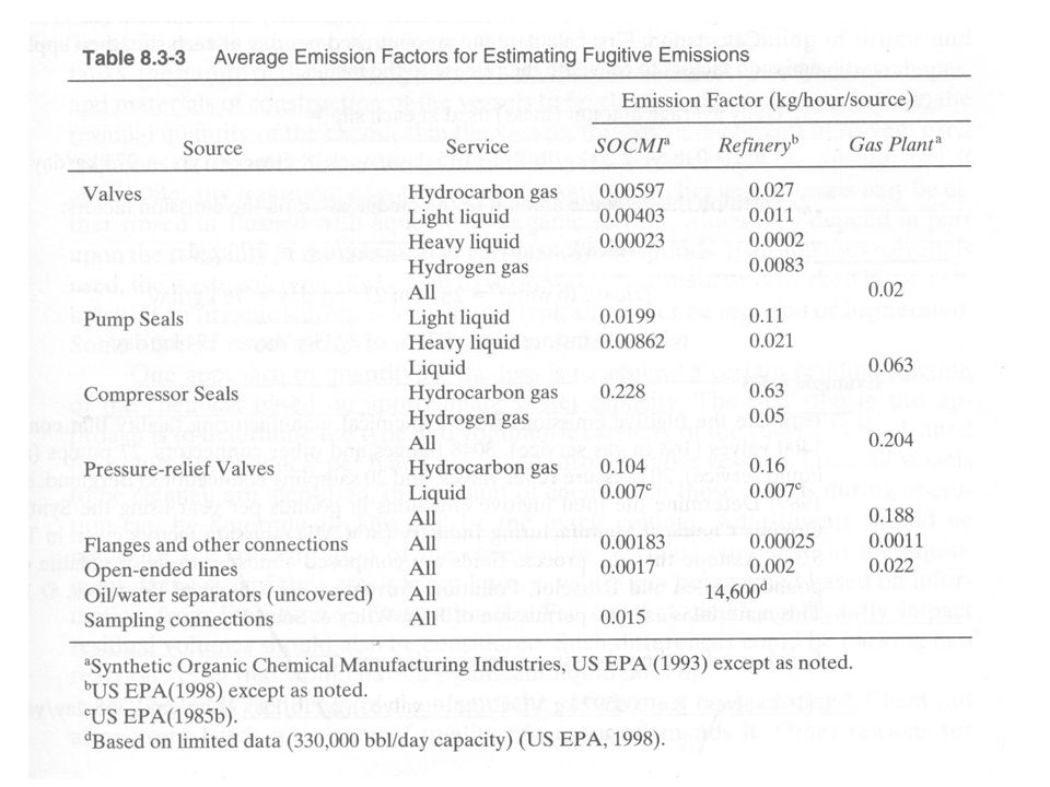
Average Emission Factors for Estimating Fugitive Emissions The units of emission factors are different from the form shown before. A light liquid is defined as a stream in which the most volatile component (present > 20% by weight) has a vapor pressure at the stream temperature of > 0.04 psi.
 has a vapor pressure at the stream temperature of > 0.04 psi..")
22
Example 8-3

24
Losses of Residuals from Cleaning of Drums and Tanks

25
Example 8.3-4 A facility purchased 42500 pounds of hydrozine this year. To determine the value of its loss as residual, the company requests us to provide estimated releases from cleaning the emptied 55-gallon drums. 1.Hydrozine is pumped from steel drums to a process vessel. 2.Its viscosity is nearly the same as water at ambient temperature. 3.The loss of water pumped from a steel drum is 2.29%. 4.Calculation: 42500 lb/yr * 2.29 lb loss/100 lb delivered = 973 lb hydrozine lost as drum residual.

26
Parts Cleaning Parts cleaning can occur in cold cleaners (where the parts are soaked in liquid solvent) or in vapor degreasers (where cleaning is accomplished through condensation of hot solvent vapor on cold parts).
 or in vapor degreasers (where cleaning is accomplished through condensation of hot solvent vapor on cold parts).")
27
Example: Solvent Emission from a Vapor Degreaser The steady-state molar flux of solvent through a column of stagnant air where is the total molar concentration of air; is the diffusivity of TCA in air; is the molar concentration of TCA.

28
Example: Solvent Emission from a Vapor Degreaser The steady-state molar flux of solvent through a column of stagnant air where is the freeboard height; is the dtotal pressure; is the vapor pressure of TCA.

29
Waste Reduction Practices for Parts Cleaning 1.Enclose solvent cleaning units; 2.Improve part draining before and after cleaning; 3.Use entirely closed-loop systems, e.g. supercritical CO2 systems; 4.Use mechanical cleaning devices, e.g. plastic bead blasting.

30
Equipment Cleaning Include: heat transfer surfaces, distillation column trays, and pipes. To reduce solvent losses, the following practices can be adopted: (1) high-pressure rinse system; (2) mechanical wipers; (3) “pigs” (objects sent through pipes to scrape them clean); (4) compressed gas; (5) blasting fouled surfaces with recyclable sand or dry ice.
 high-pressure rinse system; (2) mechanical wipers; (3) pigs (objects sent through pipes to scrape them clean); (4) compressed gas; (5) blasting fouled surfaces with recyclable sand or dry ice..")
31
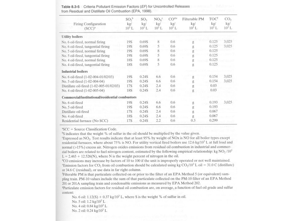
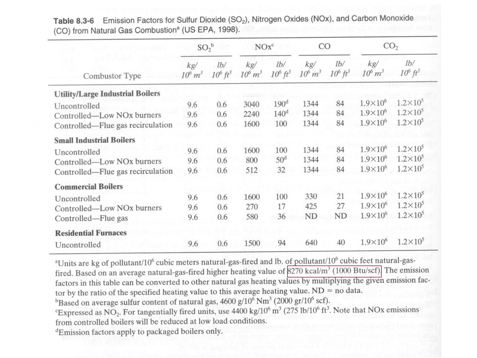
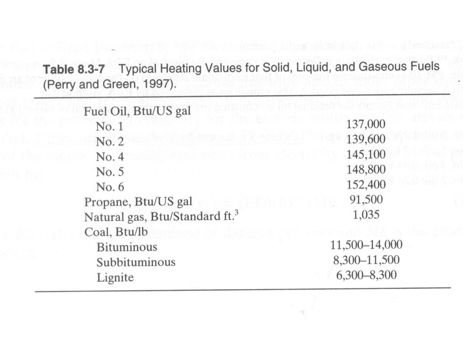
Secondary Emissions from Utility Consumption Table 8.3-5 lists emission factors for uncontrolled releases for residual and distillate oil consumption. Table 8.3-6 shows emission factors for the combustion of natural gas. These factors are based on the volume of fuel burned. In order to relate the emissions of the pollutants to energy demand, we must first know the fuel value (energy generated/volume of fuel burned) and the efficiency of the boiler supplying the energy agent (steam).
 and the efficiency of the boiler supplying the energy agent (steam)..")
32
Emissions for Fuel and Natural Gas Combustion

36
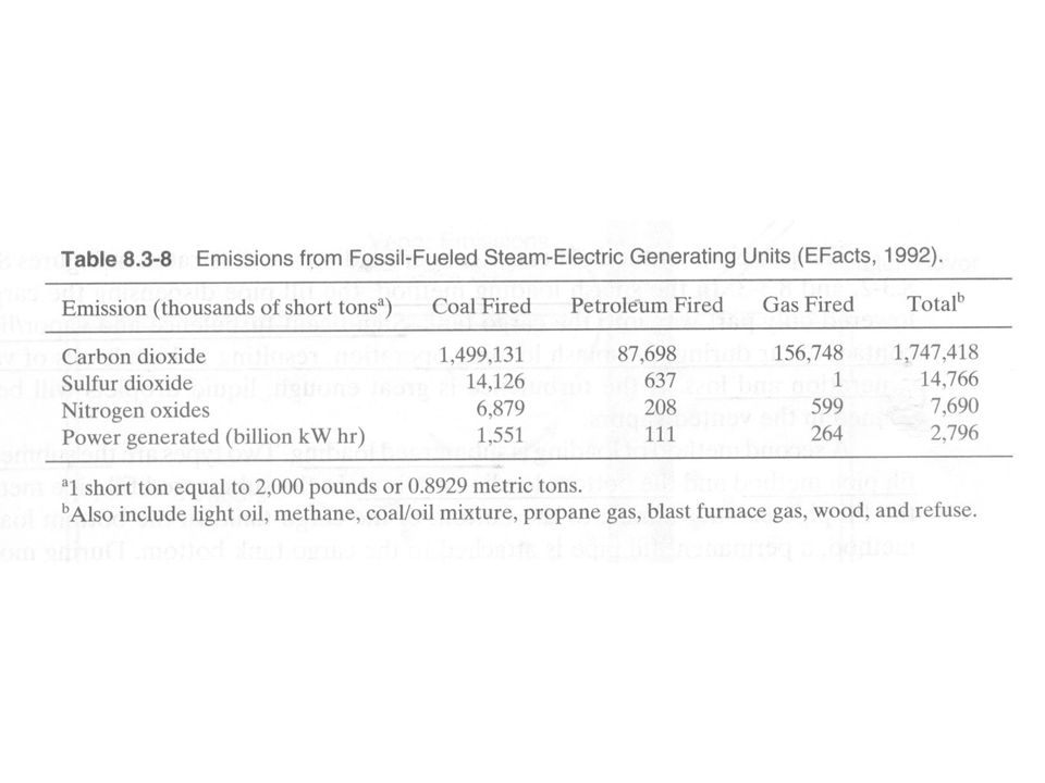
Emission Factors for Electricity Use A reasonable approximation for criteria pollutant emission factors (short tons emitted/kW hr) for electricity use can be derived from the data in Table 8.3-8 by dividing the emissions by the power generated. If not specified in the M&E balances, an efficiency for the electric motor or other devices must be included (0.75 – 0.95). Let ED be the electricity demand of the unit per year and ME be the efficiency
. Let ED be the electricity demand of the unit per year and ME be the efficiency.")
38
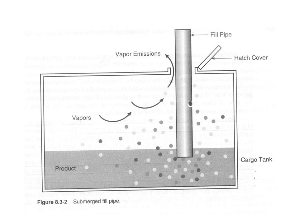
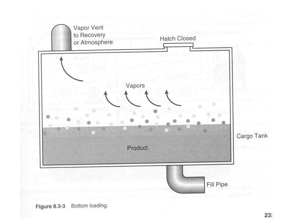
Loading Losses Loading losses occur as vapors in “empty” cargo tank are displaced to the atmosphere by the liquid being loaded into the tanks. These vapors are a composite of 1.Vapors formed in the empty tank by evaporation of residual product from previous loads; 2.Vapor transferred to the tank in vapor balance systems as product is being unloaded; 3.Vapor generated in the tank as the new product is being loaded.

39
Parameters Affecting the Quantity of Loading Losses Physical and chemical characteristics of the previous cargo. Method of unloading the previous cargo. Operations to transport the empty carrier to a loading terminal. Method of loading the new cargo. Physical and chemical characteristics of the new cargo.

40
Significant turbulence and vapor liquid contact occur, resulting in high levels of vapor generation and loss.

44
Emission Loss from Liquid Loading If evaporation rate is negligible in comparison to the displacement rate, the following equation can be used for liquids with vapor pressure below 0.68 psia.

45
Emission Rate from Liquid Loading

46
Example ABC company plans to produce and sell 50000 pounds of n-butyl lactate (NBL) this year. This product will be shipped in 55-gal drums. ABC will produce 5000 pounds per day for 10 days. Each day’s production is drummed in 30 minutes. Please estimate the daily emission rate. (Ans: 0.0037kg/day)
.")
49
Evaporative Losses from Static Liquid Pools Routine emissions may occur from open surface operation, which would include work related to open vats or tanks, solvent dip tanks, open roller coating, and cleaning or maintenance activities. More sporadic emissions may occur from liquid pools caused by events such as unintentional spills.

50
EPA Correlation

51
Estimation of Diffusion Coefficient

52
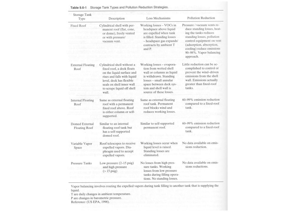
Storage Tanks (Appendix C) Storage tank can be a disastrous source of waste when weakly active reactions run away. Inadequate heat dissipation is of particular concern in the storage of bulk solids and viscous liquids. Two other sources of pollution: (1) tank bottoms and (2) standing and breathing losses.
 tank bottoms and (2) standing and breathing losses..")
53
Tank Bottoms Tank bottoms are solids or sludges (composed of rusts, soil particles, heavy feedstock constituents, and other dense materials) that that accumulate at the bottom of large storage vessels. Methods to deal with these materials: 1.They may be periodically removed and either treated via land applications or disposed of as a hazardous waste. 2.Mixers can be used as long as the materials the bottoms contain are compatible with later processing steps and will not generate more waste downstream. 3.Agents that solubilize the materials that form tank bottoms can sometimes be added to the storage tanks. However, these agents or the tank bottoms can at times generate more downstream waste than was prevented.

54
Breathing Losses There are six main kinds of storage tanks: fixed-roof, external floating-roof, internal floating-roof, domed external floating-roof, variable-vapor-space, and pressurized tanks. Breathing losses are vapor emissions from fixed-roof tanks that occur when the temperature or barometric pressure changes. Pollution prevention methods: (1) a pressure/vacuum vent, (2) narrow tanks, (3) insulated tanks, (4) vapor recovery devices, and (5) floating roof or variable- vapor-space tanks, i.e. telescoping roof and flexible diaphragm.
 a pressure/vacuum vent, (2) narrow tanks, (3) insulated tanks, (4) vapor recovery devices, and (5) floating roof or variable- vapor-space tanks, i.e. telescoping roof and flexible diaphragm..")
55
Standing Losses The floating roof can be external or it can be an internal floating roof mounted under a fixed roof. Floating-roof tanks have standing losses due to evaporation from rim, seals, deck fittings and deck seams. Standing losses are less when the seams are welded rather than bolted or riveted.

56
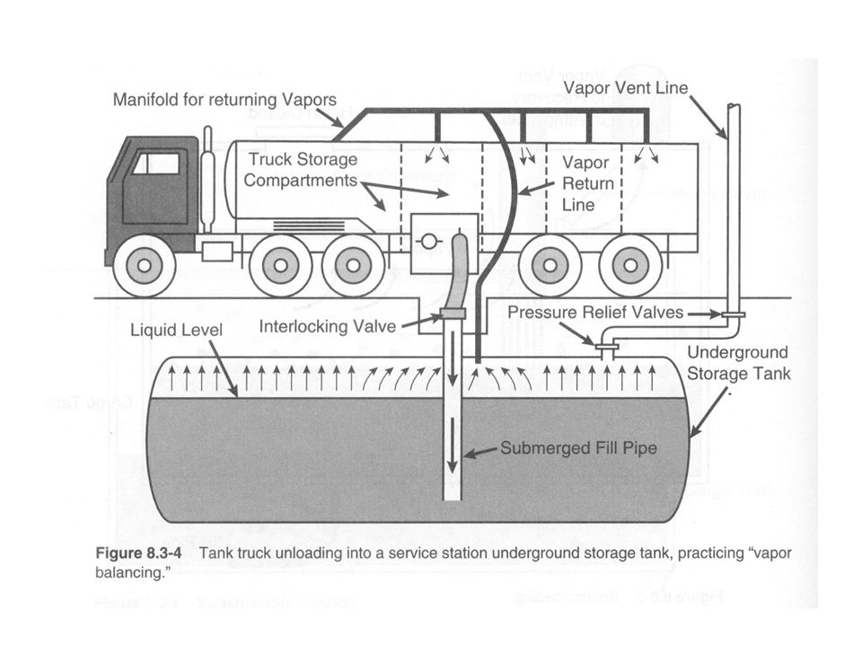
Loading and Unloading It has been estimated that as much as 12 lb of organic compounds can be lost per 1000 gal of gasoline transferred during uncontrolled railcar and tank truck loading operations. For fixed rook tanks, vapor recovery devices (trap and condense displaced gases) and vapor balance (vapors from container being filled are fed to the container being emptied) are two possible techniques to reduce emissions.
 and vapor balance (vapors from container being filled are fed to the container being emptied) are two possible techniques to reduce emissions..")
57
Withdrawal Losses Unloading operations also create waste when the storage material clings to the surfaces of the container being emptied. Unloading of floating-roof tanks exposes wet tank wall and column surfaces, which results in emissions called withdrawal losses. Emission-reduction measures: (1) off-loading devices; (2) putting transfer vessels into dedicated service; (3) reduction of wall and column area per fluid volume.
 off-loading devices; (2) putting transfer vessels into dedicated service; (3) reduction of wall and column area per fluid volume..")
58
Waste Reduction Measures for Storage Containers Reuse shipping containers and storage bins Select appropriate-sized containers

Similar presentations


>")

 Activities That Produce Used Oil n Routine oil changes or repairs n Oily parts drip when placed on the floor or are carried.>")


