Download presentation
Presentation is loading. Please wait.

1
Major Underground Design John Perez

2
Underground Engineering Design Practices Three Phase Circuit –Infrastructure: Ductbanks & Manholes All three phase ductbanks are 4” & 2” PVC conduits encased in 3 inches of concrete –Conduits are separated by 3 inches held in place with spacers (every 4’) –One 4/0 Copper bare Neutral per circuit feeder is placed above the spacers within concrete Ductbanks have 30” of cover in private property, 36” in public ROW and 48” of cover in substations Ductbanks are sized in the planning stage between Developers, Distribution Planning and Underground Engineering
 –One 4/0 Copper bare Neutral per circuit feeder is placed above the spacers within concrete Ductbanks have 30 of cover in private property, 36 in public ROW and 48 of cover in substations Ductbanks are sized in the planning stage between Developers, Distribution Planning and Underground Engineering")
3
Underground Engineering Design Practices –Ductbanks & Manholes (continued) Manholes are spaced approximately 350’-400’ and encased in flowable fill –Distances may vary depending on ductbank routing/ design –Typically manhole alignment allows the duct to entire on center of the corners (diamond) Manholes range from 5’x5’x6’ to12’x12’x12’ according to the ductbank size –Manholes are H20 rated and contain thin wall knockouts in the corners –12” diameter sump in the middle to allow for pumping
 Manholes are spaced approximately 350’-400’ and encased in flowable fill –Distances may vary depending on ductbank routing/ design –Typically manhole alignment allows the duct to entire on center of the corners (diamond) Manholes range from 5’x5’x6’ to12’x12’x12’ according to the ductbank size –Manholes are H20 rated and contain thin wall knockouts in the corners –12 diameter sump in the middle to allow for pumping")
4
Underground Engineering Design Practices Color Coded Corner window Hooks/ Racks Circuit Tag Permanent Ladder Neutrals

5
Underground Engineering Design Practices –Design Philosophy Substations Ductbanks are typically 33-4” & 3-2” PVC conduits inside the station with 6-4” conduits between substation switchgear tie cubicles –Provides Cooling conduits, Circuit reroutes and new feeder circuits –750 kCM, Copper, EPR conductors are used for circuit exits (both 15 kV & 35 kV circuits) Dips Installed to avoid overhead conflicts, customer requested jobs, underground conversion areas Circuit Dips when feasible contain an “Express Feeder” –Express feeders are fed directly between overhead “P-Switches” and do not feed any padmount equipment –Circuits dips are fed with 750 kCM, Copper, EPR conductors (both 15 kV & 35 kV circuits) –Separate Risers feed customer loads –Avoids prolonged outages (SADI, SAFI) due to Padmount Switchgear replacements/ failures Loop Feeds CPS Energy padmount transformers are fed between: Risers; Riser to Padmount Switchgears; and Padmount Switchgear Padmount Switchgears are fed from a solid blade “P Switch” with 4/0 AWG Copper EPR conductors or greater Padmount transformers are typically fed with bundled #2 AWG Aluminum XLPE 15 kV or 1/0 AWG EPR Aluminum 35 kV conductors Padmount transformer usually have three 4” PVC conduits in the slab Loop connected kVA are a maximum of 2,500 kVA and 6,000 kVA for 15 kV primary and 35 kV primary respectively, with open points at the load midpoint
 Dips Installed to avoid overhead conflicts, customer requested jobs, underground conversion areas Circuit Dips when feasible contain an Express Feeder –Express feeders are fed directly between overhead P-Switches and do not feed any padmount equipment –Circuits dips are fed with 750 kCM, Copper, EPR conductors (both 15 kV & 35 kV circuits) –Separate Risers feed customer loads –Avoids prolonged outages (SADI, SAFI) due to Padmount Switchgear replacements/ failures Loop Feeds CPS Energy padmount transformers are fed between: Risers; Riser to Padmount Switchgears; and Padmount Switchgear Padmount Switchgears are fed from a solid blade P Switch with 4/0 AWG Copper EPR conductors or greater Padmount transformers are typically fed with bundled #2 AWG Aluminum XLPE 15 kV or 1/0 AWG EPR Aluminum 35 kV conductors Padmount transformer usually have three 4 PVC conduits in the slab Loop connected kVA are a maximum of 2,500 kVA and 6,000 kVA for 15 kV primary and 35 kV primary respectively, with open points at the load midpoint")
6
Underground Engineering Design Practices Loop Feeds (continued) When designs require manholes and/or padmount switchgears, the transformers are fed from manholes only –To allow future expansion with minimal disruption transformers are looped through manholes
 When designs require manholes and/or padmount switchgears, the transformers are fed from manholes only –To allow future expansion with minimal disruption transformers are looped through manholes")
7
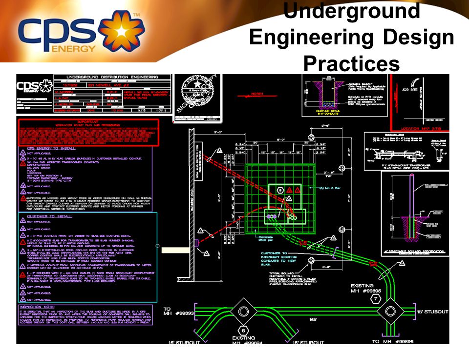
Underground Engineering Design Practices –Job Sketches 1-lines are created for 3 or more transformers and kept on the server –Dashed lines indicate planned infrastructure/ cable installation –Solid lines indicate in the field conditions –Open points, circuit numbers, footages and size/number of conduits on the drawing MicroStation sketches are required for detailed drawings –Padmount details showing rebar layouts, conduit locations –Manhole/ ring & cover apron specifications –Ductbank requirements and routing –Cable pulling schedule –Manhole cable routing GIS also logs detailed information –Circuit conductivity & general placement of facilities –Circuit number, facilities information, open points, etc

8
Underground Engineering Design Practices 1-line example

9
Underground Engineering Design Practices

Similar presentations


 Loops Stacey Mighty Malcolm Distribution.>")


