Download presentation
Presentation is loading. Please wait.

1
CFD Modelling of River Flow By Dr. D.R. Kaushal Associate Professor Department of Civil Engineering IIT Delhi

2
CFD Modeling of multiphase flows CFD modeling consists of: 1.Division of the domain into discrete control volumes using GAMBIT 2.Integration of the governing equations on the individual CV to construct algebraic equations for the discrete dependent variables using FLUENT 3.Linearization of the discretized equations and solution of the resultant equation system to yield updated values of the dependent variables using FLUENT

3
Modeling multiphase flows using CFD 1. The Eulerian Model (Euler-Euler Approach) The Eulerian model is the most complex of the multiphase models. It solves a set of momentum and continuity equations for each phase. Coupling is achieved through the pressure and interphase exchange coefficients. Kaushal, D.R., Thinglas, T. and Tomita, Y., CFD modeling for pipeline flow of fine particles at high concentration, Int. J. of Multiphase Flow, Under Review, 2011. (slurry flow of glass beads with mean diameter of 125 m for velocity up to 5m/s at volumetric concentrations of 30%, 40% and 50% for each velocity)
 The Eulerian model is the most complex of the multiphase models. It solves a set of momentum and continuity equations for each phase. Coupling is achieved through the pressure and interphase exchange coefficients. Kaushal, D.R., Thinglas, T. and Tomita, Y., CFD modeling for pipeline flow of fine particles at high concentration, Int. J. of Multiphase Flow, Under Review, (slurry flow of glass beads with mean diameter of 125 m for velocity up to 5m/s at volumetric concentrations of 30%, 40% and 50% for each velocity).")
4
Modeling multiphase flows using CFD 2. The Mixture Model (Euler-Euler Approach) The mixture model is designed for two or more phases (fluid or particulate). As in the Eulerian model, the phases are treated as interpenetrating continua. The mixture model solves for the mixture momentum equation and prescribes relative velocities to describe the dispersed phases, hence applicable for medium concentrations up to 20% by volume. 1.Kaushal, D.R., Kumar, A. and Tomita, Y., Flow of mono-dispersed particles through horizontal bend, Int. J. of Multiphase Flow, Under Review, 2011. 2.Kaushal, D.R., Kumar, A. and Tomita, Y., Flow of bi-modal particles through horizontal bend, Int. J. of Multiphase Flow, Under Review, 2011. (slurry flow of silica sand with mean diameter of 450 m for velocity up to 3.6 m/s at volumetric concentrations of 4%, 9% and 17% for each velocity. Fly ash is added in different proportions for bi-modal slurry flow study.)
 The mixture model is designed for two or more phases (fluid or particulate). As in the Eulerian model, the phases are treated as interpenetrating continua. The mixture model solves for the mixture momentum equation and prescribes relative velocities to describe the dispersed phases, hence applicable for medium concentrations up to 20% by volume. 1.Kaushal, D.R., Kumar, A. and Tomita, Y., Flow of mono-dispersed particles through horizontal bend, Int. J. of Multiphase Flow, Under Review, Kaushal, D.R., Kumar, A. and Tomita, Y., Flow of bi-modal particles through horizontal bend, Int. J. of Multiphase Flow, Under Review, (slurry flow of silica sand with mean diameter of 450 m for velocity up to 3.6 m/s at volumetric concentrations of 4%, 9% and 17% for each velocity. Fly ash is added in different proportions for bi-modal slurry flow study.).")
5
Modeling multiphase flows using CFD 3. The Discrete Phase Model (Euler-Lagrange Approach) The fluid phase is treated as a continuum by solving the time-averaged Navier-Stokes equations. Dispersed phase is solved by tracking a large number of particles through the calculated flow field. The dispersed phase can exchange momentum, mass, and energy with the fluid phase. A fundamental assumption made in this model is that the dispersed second phase occupies a low volume fraction (up to 10% by volume). The particle trajectories are computed individually at specified intervals during the fluid phase calculation. Kaushal, D.R., Thinglas, T. and Tomita, Y., Experimental Investigation on Optimization of Invert Trap Configuration for Solid Management, Powder Technology, Accepted.
 The fluid phase is treated as a continuum by solving the time-averaged Navier-Stokes equations. Dispersed phase is solved by tracking a large number of particles through the calculated flow field. The dispersed phase can exchange momentum, mass, and energy with the fluid phase. A fundamental assumption made in this model is that the dispersed second phase occupies a low volume fraction (up to 10% by volume). The particle trajectories are computed individually at specified intervals during the fluid phase calculation. Kaushal, D.R., Thinglas, T. and Tomita, Y., Experimental Investigation on Optimization of Invert Trap Configuration for Solid Management, Powder Technology, Accepted..")
6
Modeling multiphase flows using CFD 4. The Volume of Fluid (VOF) model The VOF model can model two or more immiscible fluids The VOF formulation relies on the fact that two or more fluids (or phases) are not interpenetrating VOF solves single set of momentum equations VOF tracks the volume fraction of each of the fluids throughout the domain VOF is widely used for open channel flows
 model The VOF model can model two or more immiscible fluids The VOF formulation relies on the fact that two or more fluids (or phases) are not interpenetrating VOF solves single set of momentum equations VOF tracks the volume fraction of each of the fluids throughout the domain VOF is widely used for open channel flows.")
7
Governing Equations of Discrete Phase Model (DPM) Reynolds-averaged Navier-Stokes equations representing transport equations for the mean flow velocities Source term in the momentum equation due to presence of the particulate phase and for each cell C Boussinesq hypothesis, relating the Reynolds stresses with the mean velocity gradients (Hinze, 1975)
 Reynolds-averaged Navier-Stokes equations representing transport equations for the mean flow velocities Source term in the momentum equation due to presence of the particulate phase and for each cell C Boussinesq hypothesis, relating the Reynolds stresses with the mean velocity gradients (Hinze, 1975)")
8
RNG based k turbulence model Force balance on the particle in x- direction

9
Sewer/canal sediment management by Invert Trap

10
Experimental Study on Invert Trap

11
Experimental Setup contd.. Pictorial View of Experimental Set-Up Collecting Tank Channel Sediment injector Pump Invert Trap Inlet Tank Regulator Re-circulating Pipe Experimental Set-Up at Simulation Laboratory, Civil Engineering Department, IIT Delhi Video Clip

12
Invert Trap Configurations

18
Variation of retention ratio with slot size

19
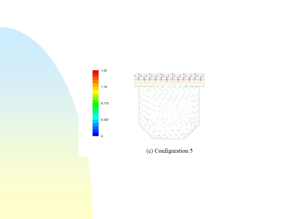
Three-dimensional geometry for Configuration 5 used in CFD computations

20
Grid Generation using GAMBIT Cross-sectional mesh used in CFD

21
ZonesCell depthCell length Number of Mesh cells Channel (upstream of invert trap) 3mm5 mm70,000 Invert Trap1 mm3 mm20,000 Channel (downstream of invert trap) 3mm5 mm40,000 Details of 3D mesh generated using GAMBIT software
 3mm5 mm70,000 Invert Trap1 mm3 mm20,000 Channel (downstream of invert trap) 3mm5 mm40,000 Details of 3D mesh generated using GAMBIT software")
22
CFD based velocity contours in m/s at flow rate of 9.95 l/s

24
Fluid velocity vectors in m/s for slot size of 15 cm at flow rate of 9.95 l/s

26
CFD based particle trajectories at flow rate of 9.95 l/s

28
CFD-based retention ratio for Sand1 particles for different slot sizes for Configuration4

29
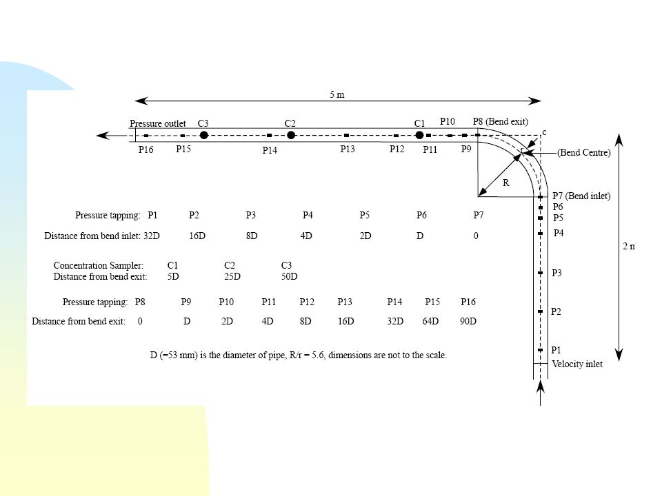
List of Selected Long-Distance Slurry Pipelines ProductProject LocationLengthYear of (Km)Operation Iron ConcentrateIndia (BRPL Orissa)2202009 Iron Ore tailingsIndia (BRPL Orissa)182009 Bauxite OreBrazil2442007 Iron ConcentrateBrazil4002007 Iron ConcentrateChina1772007 Iron ConcentrateIndia (Essar Steel)2682005 Copper ConcentrateChile1032004 Copper/Zinc ConcentratePeru3022001 Copper ConcentrateChile2031998 Copper ConcentrateArgentina3121997 Iron ConcentrateChina1051997 Copper ConcentrateChile1671990 CoalUSA16751979 CoalUSA4401970
Operation Iron ConcentrateIndia (BRPL Orissa) Iron Ore tailingsIndia (BRPL Orissa) Bauxite OreBrazil Iron ConcentrateBrazil Iron ConcentrateChina Iron ConcentrateIndia (Essar Steel) Copper ConcentrateChile Copper/Zinc ConcentratePeru Copper ConcentrateChile Copper ConcentrateArgentina Iron ConcentrateChina Copper ConcentrateChile CoalUSA CoalUSA")
30
Experimental Set-Up at Fluid Mechanics Laboratory, IIT Delhi Slurry pipeline transportation system

32
CFD based pressure drop profile in slurry pipe bend

33
CFD based concentration profiles profile in slurry pipe bend

34
CFD simulation of hydraulic jump

35
CFD simulation of drop structure

36
CFD simulation of drop gated spillway

37
CFD simulation of cantilever outfall

38
CFD simulation of Ganga river The hydraulic characteristics of natural river flood plains are not well understood at present. This is due to the problems encountered in monitoring spatially distributed patterns of flow depths, velocity, turbulence characteristics etc. For designing the flood protection strategies, it is very important for river engineers to accurately predict water levels that may be expected due to any flood discharge. One of the consequences resulting from the more recently recognized hazards of climate change is the potential to increase the levels and occurrence of flooding worldwide. Meandering channel flows being highly complicated are a matter of recent and continued research.

39
3D geometry is developed using (x,y,z) coordinates obtained from DEM CFD based simulations are done on the basis of discharge data Based on CFD analysis, meandering patterns are obtained CFD results will be studied to suggest flood protection strategies and preventive measures for protecting banks from erosion
 coordinates obtained from DEM CFD based simulations are done on the basis of discharge data Based on CFD analysis, meandering patterns are obtained CFD results will be studied to suggest flood protection strategies and preventive measures for protecting banks from erosion")
40
CFD based deposition pattern in meandering river

42
END…..….

Similar presentations


 Chapter 9: FLOWS IN PIPE>")

