Download presentation
Presentation is loading. Please wait.

1
1 “CFD Analysis of Inlet and Outlet Regions of Coolant Channels in an Advanced Hydrocarbon Engine Nozzle” Dr. Kevin R. Anderson Associate Professor California State Polytechnic University at Pomona Department of Mechanical Engineering Thermal/Fluids Engineer, Swales Aerospace Faculty Part Time T&FSE, NASA-JPL TFAWS 2004 Thermal & Fluids Analysis Workshop Aerothermal / CFD Paper 109-A0019 JPL Pasadena, CA August 30 – September 3, 2004 Pasadena Center, Pasadena, CA

2
2 CFD Analysis Required to Model Channel Outlet Regions Background: AHEP – Advanced Hydrocarbon Engine Program Air Force sponsored research contracted Swales Aerospace to perform CFD analysis

3
3 CFD Analysis Required to Model Channel Outlet Regions Goal: Estimate Convective Heat Transfer Coefficient On Hot Gas Wall At Inlet And Outlet Region Of Rectangular Channel A A Coolant Inlet Section A-A Coolant Outlet Combustion Chamber Geometry

4
4 Injector Mounting Flange Stresses Copper Combustor Liner Stresses Electroformed Nickel Structural Closeout Stresses Copper/EF Nickel Bond Joint Stresses Injector Exit Plane Combustion Chamber Cross-Section Combustor Geometry

5
5 Combustor Liner Dimensions Vacuum Plasma Sprayed GRCop-84 Combustor Liner Coolant Channel Electroformed Nickel Structural Closeout 300 R Throat Cross-section All Dimensions are in Inches 1210 R 270 R 0.140 0.30 0.035 0.050

6
6 Bounding Calculations Based upon inlet flow rates and LN 2 properties – Reynolds Number Flow Rate (lb/s)Re inlet ×10 5 Re outlet ×10 5 0.70.81538.6 1.01.16555.1 1.21.39866.1 Thus, flow is modeled as Turbulent
Re inlet ×10 5 Re outlet × Thus, flow is modeled as Turbulent")
7
7 Bounding Calculations Based upon inlet and outlet speed of sound in LN 2 – Mach Number Flow Rate (lb/s)Ma inletMa outlet 0.70.0730.171 1.00.1050.244 1.20.1260.293 Thus, flow is modeled as Incompressible
Ma inletMa outlet Thus, flow is modeled as Incompressible")
8
8 CFD Modeling Methodology GAMBIT © 2.0 Used to Build Computational Grid FLUENT © 6.0 3-D Finite Volume Incompressible, Viscous Internal flow Standard k- Turbulence Model Internal Flow Convective Heat Transfer FLUENT User Defined Fluid Option for LN 2 NIST 12 Database Used to Obtain LN 2 Properties:

9
9 CFD Modeling Methodology

10
10 Governing Equations Conservation of Mass Conservation of Momentum

11
11 Governing Equations Conservation of Energy

12
12 Governing Equations Conservation of Energy - Segregated solver does not include Pressure Work or Kinetic Energy terms, which are negligible for incompressible flows - Viscous Dissipation terms which describe the thermal energy created by the viscous shear in the flow must be included since Brinkman number: - Br ~ 1.14, 2.3, 3.4, Viscous Heating present

13
13 Governing Equations Standard k- Turbulence Model

14
14 Governing Equations Turbulent Eddy Viscosity Model Constants

15
15 CFD Model Solution FLUENT © Segregated Solver - Finite Volume Discretization - Linearization of Discretized Equations Implicit Linearization results in a system of linear equations for each cell in the domain Point implicit Gauss-Seidel linear equation solver used in conjunction with an Algebraic Multigrid Method (AMG) to solve the resultant scalar system
 to solve the resultant scalar system")
16
16 CFD Model Solution Overview of the Segregated Solution Method Mesh independence study showed approx. 70,000 Finite Volumes required for grid independent converged results UPDATE PROPERTIES SOLVE MOMENTUM EQUATIONS SOLVE PRESSURE-CORRECTION (CONTINUITY) EQUATION UPDATE PRESSURE, FACE MASS FLOW RATE SOLVE ENERGY, TURBULENCE AND OTHER SCALAR EQUATIONS CONVERGED ? STOP
 EQUATION UPDATE PRESSURE, FACE MASS FLOW RATE SOLVE ENERGY, TURBULENCE AND OTHER SCALAR EQUATIONS CONVERGED . STOP.")
17
17 Boundary Conditions A A Coolant Inlet Section A-A Coolant Outlet Mass Flow Rate Inlet BC Supply LN 2 : 140 R 6000 psia Pressure Outlet BC Exit LN 2 : 285 R 4870 psia Heat Flux BC 97 BTU/in 2 -s (50.3×10 6 BTU/hr-ft 2 ) k- log-law of the wall wall functions
 k- log-law of the wall wall functions")
18
18 3-D FLUENT CFD Model Grid Surfaces Outline

19
19 Detail View of Mesh Near Channel Inlet Region

20
20 Detail View of Mesh Near Channel Outlet Region

21
21 Flow rate = 0.7 lb/s Velocity Vectors Near Inlet

22
22 Flow rate = 0.7 lb/s Velocity Vectors Near Outlet

23
23 Flow rate = 0.7 lb/s Contours of h (BTU/hr-ft 2 -R)
")
24
24 Flow rate = 0.7 lb/s Contours of h (BTU/hr-ft 2 -R) Near Inlet
 Near Inlet")
25
25 Flow rate = 0.7 lb/s Contours of h (BTU/hr-ft 2 -R) Near Outlet
 Near Outlet")
26
26 Flow rate = 0.7 lb/s Contours of h (BTU/hr-ft 2 -R) Near Inlet
 Near Inlet")
27
27 Flow rate = 0.7 lb/s Contours of h (BTU/hr-ft 2 -R) Near Outlet
 Near Outlet")
28
28 Flow rate = 1.0 lb/s Velocity Vectors Near Inlet

29
29 Flow rate = 1.0 lb/s Velocity Vectors Near Outlet

30
30 Flow rate = 1.0 lb/s Contours of h (BTU/hr-ft 2 -R)
")
31
31 Flow rate = 1.0 lb/s Contours of h (BTU/hr-ft 2 -R) Near Inlet
 Near Inlet")
32
32 Flow rate = 1.0 lb/s Contours of h (BTU/hr-ft 2 -R) Near Outlet
 Near Outlet")
33
33 Flow rate = 1.0 lb/s Contours of h (BTU/hr-ft 2 -R) Near Inlet
 Near Inlet")
34
34 Flow rate = 1.0 lb/s Contours of h (BTU/hr-ft 2 -R) Near Outlet
 Near Outlet")
35
35 Flow rate = 1.2 lb/s Velocity Vectors Near Inlet

36
36 Flow rate = 1.2 lb/s Velocity Vectors Near Outlet

37
37 Flow rate = 1.2 lb/s Contours of h (BTU/hr-ft 2 -R)
")
38
38 Flow rate = 1.2 lb/s Contours of h (BTU/hr-ft 2 -R) Near Inlet
 Near Inlet")
39
39 Flow rate = 1.2 lb/s Contours of h (BTU/hr-ft 2 -R) Near Outlet
 Near Outlet")
40
40 Flow rate = 1.2 lb/s Contours of h (BTU/hr-ft 2 -R) Near Inlet
 Near Inlet")
41
41 Flow rate = 1.2 lb/s Contours of h (BTU/hr-ft 2 -R) Near Outlet
 Near Outlet")
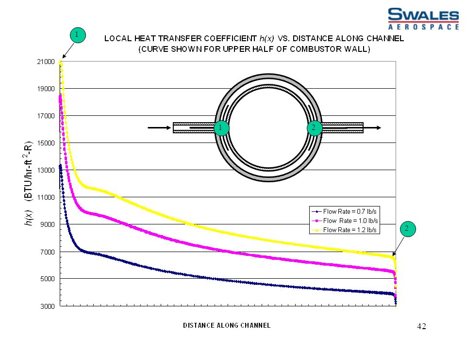
42
42 12 1 2 2
43
43 Comparison of Overall Convective Heat Transfer Coeff.

Similar presentations


