Download presentation
Presentation is loading. Please wait.

1
PHYSICAL MODELING OF BREACH FORMATION Large scale field tests Kjetil Arne Vaskinn, Sweco Gröner Norway

2
Test site Test area at the reservoir lake Røssvatnet Tustervassdammen Røssvatnet

3
Test area at the reservoir lake Røssvatnet

4
Instrumentation Water levels (stage-discharge measurements): Upstream of the dam Downstream of the dam Discharge through the gates at Røssvassdammen Photo (several points) Video (3 different cameras) Pressure sensors in the dam Breach sensors
: Upstream of the dam Downstream of the dam Discharge through the gates at Røssvassdammen Photo (several points) Video (3 different cameras) Pressure sensors in the dam Breach sensors")
5
Large scale field-tests 2002

6
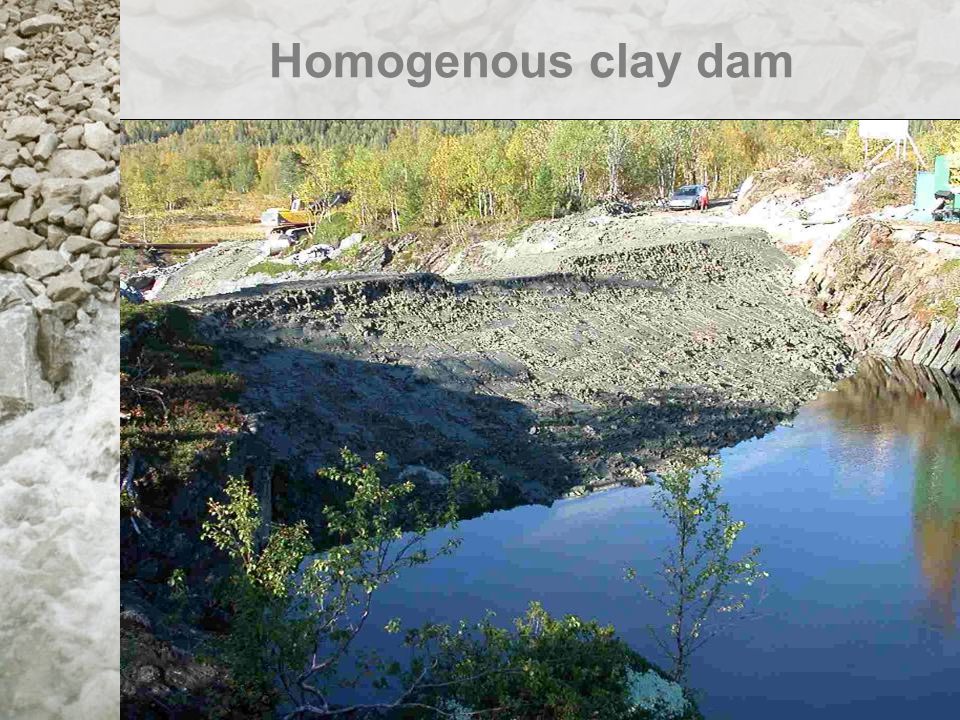
2 m 2.0 1 6 m 1 Rock 1 Clay, moisture content 30%, placed in 0.15 m layers compacted with dozer Homogenous clay dam

8
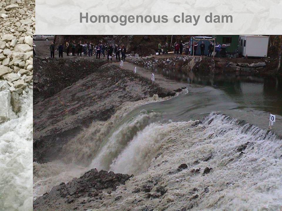
A 0.5 m deep and 3 m wide channel at the top of the dam for initiation of the breach Due to high water content in the clay deposit (w = 28-33%) construction of the dam became difficult. To improve construction the layer thickness was increased to 0.4 m and the compaction pressure was reduced. Homogenous clay dam

16
Water elevation and discharge Homogenous clay dam

17
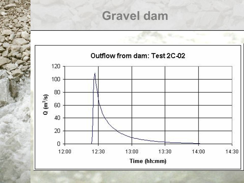
2 m 5m Concrete sill Clay Rock Homogenous (minimum cohesive) dam. Gravel 0-60 mm, fines (0,074mm)<5%, 4 mm<d 50 <10 mm, d max <60 mm 0.5 meter layer, compaction by 4 tons roller compacter, 2 layer with pore pressure sensors. Gravel dam
<5%, 4 mm<d 50 <10 mm, d max <60 mm 0.5 meter layer, compaction by 4 tons roller compacter, 2 layer with pore pressure sensors. Gravel dam.")
21
Left hand side Right hand side Gravel dam

23
Large scale field-tests 2003

24
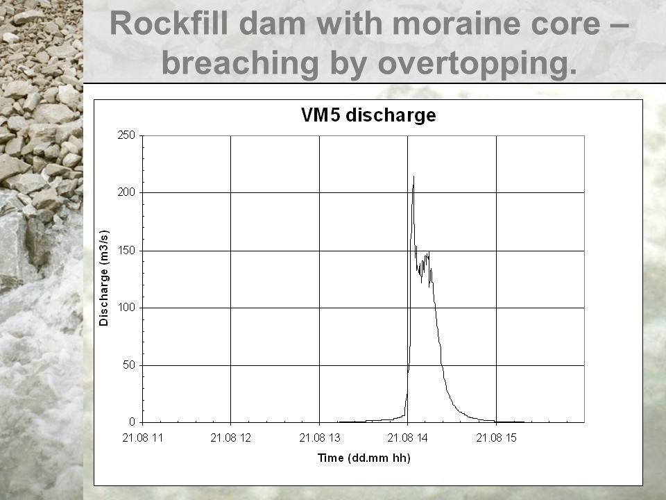
Rockfill dam with moraine core – breaching by overtopping. 5.9m 1 1.5 3m 1 4 0.65m 1.5m Concrete sill and V- notch weir Clay Rock 0.24m deep and 8 m wide notch in dam crest during breach test 2 Rock from tunnel spoil 0-500mm 3 Rockfill 300-400mm 2 1 3 Defects built into dam for test of leakage detection Pressure tranceducers Moraine 1

25
Rockfill dam with moraine core – breaching by overtopping.

33
Rockfill dam with moraine core – breaching by piping/internal erosion 6m 1 1.5 1 4 Concrete sill and V- notch weir 6m Small defect Large defect 3m Clay Rock Defects built into dam for initiation of piping, two 200 mm half-pipes embedded in uniform sand Moraine, vibratory compaction, 0.5 m layer thickness 1 2 Rock from tunnel spoil 0-500mm, vibratory compaction, 1 m layer thickness 3 Rockfill 3-400mm, vibratory compaction, 1 m layer thickness 1 2 3

34
Rockfill dam with moraine core – breaching by piping/internal erosion

36
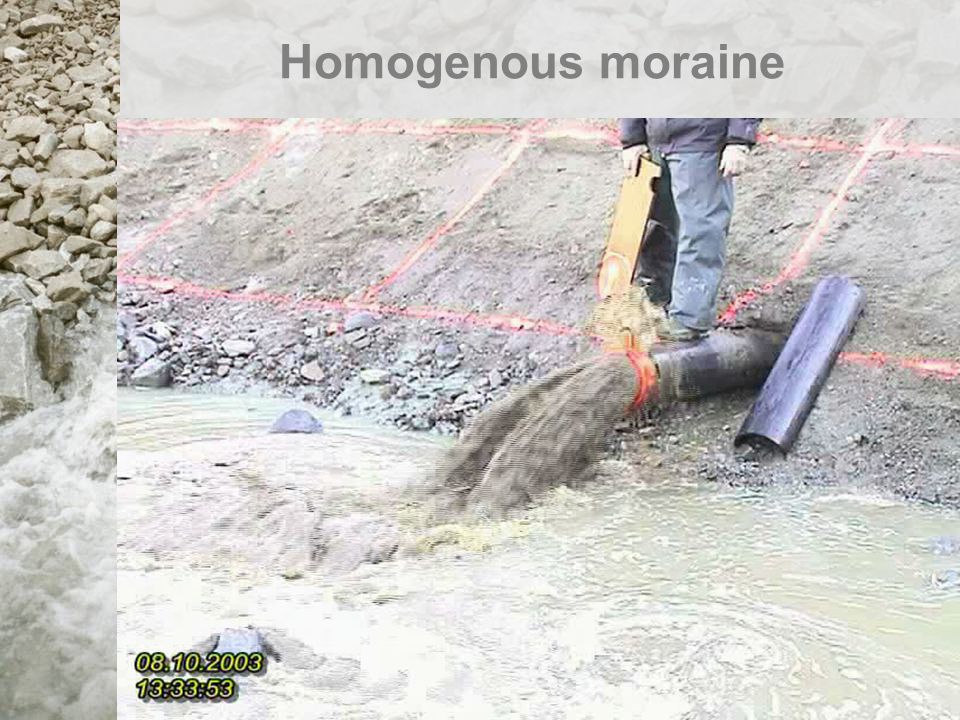
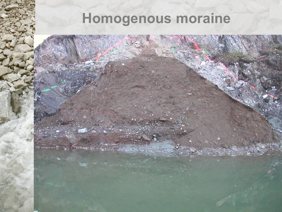
Homogenous moraine 4.5m 1 1.3 Concrete sill and V- notch weir 4.5m 3m Clay Rock Defect built into dam for initiation of piping. 200 mm half-pipe with slots embedded in uniform sand Moraine, vibratory compaction, 0.5 m layer thickness 1 1 1 2 Remaining portions of previous test dam 2 2

37
Homogenous moraine

42
Analysis of the data has started and is likely to continue for some years. The data will assist in the development of understanding and validation of predictive models. Prior to this analysis, some initial, broad observations may be made based upon field observations and data analysis to date. These include the following: Summary / conclusions

43
1.The failure processes of the different embankments have been observed. 2.Features such as cracking, arching (pipe formation), headcut formation and progression were all observed. 3.Existing breach models does not accurately simulate many of these features. Summary / conclusions
, headcut formation and progression were all observed. 3.Existing breach models does not accurately simulate many of these features. Summary / conclusions.")
44
4.The first phase in the external erosion of the downstream slope due to overtopping is slow and very gradual. 5.When the scour and unraveling finally reaches the upstream edge of the dam crest, the breaching is rapid and dramatic. 6.The same general observations were made for the rockfill, gravel and clay dams. 7.The opening of the breach first progresses down to base of the dam, before it expands laterally. The sides of the breach were very steep, almost vertical, in all three materials. Summary / conclusions

45
8.The rate of breach growth for the homogeneous clay and gravel dams was not as expected. 9.The clay dam failure more quickly, whilst the gravel dam more slowly than expected. It is likely that this was due to the condition of material and nature of construction / compaction. This demonstrates the significant impact that material condition and construction method may have on breach formation and hence the need to consider these aspects within predictive models. Summary / conclusions

46
10.The internal erosion process, initiated at the defects built into the moraine core of the rockfill dam (Test 2-2003), took a very long time to develop, even in this dam with no filters between the moraine core and the downstream rockfill. 11.Breaching of the dam did not take place until the erosion had proceeded up to the dam crest, and then the dam failed by overtopping as in Test 1- 2003, but the breach opening was not so wide. Summary / conclusions

47
12.The difference in rate of embankment failure for the homogeneous moraine embankment and the composite moraine / rockfill embankment was significant. This demonstrates the importance of the interaction between layers of material within a composite structure. This has implications for overall dam stability and in the development of predictive breach models. Summary / conclusions

48
13.Many of the field test scenarios simulated typical rockfill embankment dams. As such, there was surprise that the rate and mechanisms of failure observed were typically more resistant than existing analyses and guidelines prescribe. Summary / conclusions

Similar presentations


 Worldwide.>")


, Inc. September 2005 1 Canatuan Tailings Management Completion of Stage 1 Tailings Management Facilties Gossan Dam and.>")


