Download presentation
Presentation is loading. Please wait.

1
The Asphalt Core Embankment Dam A Very Competitive Alternative
Prof. Dr. Kaare Höeg Norwegian Geotechnical Institute (NGI) and University of Oslo Athens, Greece,19 Nov. 2009
 and University of Oslo. Athens, Greece,19 Nov")
2
Svartevann Earth Core Rockfill Dam (129 m), Norway
, Norway")
3
Svartevann Dam under construction

4
Oddatjörn Earth Core Rockfill Dam, Norway (145 m)
")
5
Oddatjörn Dam

6
Storglomvatn Asphalt Core Dam, Norway(125m)
plinth

7
Storglomvatn Dam near completion (125m)
")
9
Compaction of asphalt concrete core and transition zones

10
Experience with Asphalt Core Dams
100 dams have been built, most in Europe and China, now also in North and South America; 20 are currently under construction or final design; first ones built in the early 1960s (Germany and Austria; 15 built in Norway; 3 more are now under construction/final design;

11
Field Monitoring - The first dams with asphalt core were heavily instrumented and thoroughly analysed to better understand dam and core behaviour. - Field performance has been excellent, with no recorded leakage through core or the core-plinth interface at the base of the core.

12
Laboratory testing of asphalt concrete
For each new dam and site tests are performed to determine the optimum asphalt concrete mix using: the available (local) aggregates (0-18 mm); filler material ( mm); grade of bitumen available. The goal is to achieve a core with low permeabilty and flexible and ductile stress-strain behaviour with the required strength.
 aggregates (0-18 mm); filler material ( mm); grade of bitumen available. The goal is to achieve a core with low permeabilty and flexible and ductile stress-strain behaviour with the required strength.")
13
Laboratory testing (cont’d)
Full advantage has been taken of all the laboratory and field research done for asphalt concrete used in road- and airfield pavements.

14
Cross-section through a triaxial specimen

15
Fuller’s grain size curve for aggregates

17
Triaxial compression tests showing effect of confining stress level

18
Splitting test of cylindrical specimen to determine tensile strength (Brazilian test)
")
19
Beam test to determine flexural (tensile) strength and strain before crack opens
 strength and strain before crack opens")
20
Test to create crack in specimen

21
Regain of tensile strength under compressive stress and sealing of crack

22
Investigation of self-healing of crack

23
Results of self-sealing test

24
Triaxial test – cyclic loading superimposed on static loading (to simulate eartquake loading)
")
25
Cyclic strain and residual strain during test

26
Pre-cyclic vs. post-cyclic stress-strain behaviour
Deviator stress (MPa)
")
27
Asphalt concrete placed in core
Air porosity in asphalt core should be less than 3% to ensure very low permeabilty (10-10 m/s); Placed and compacted in layers cm thick; 2 to 4 layers per day depending on required rate of construction; Core width usually cm depending on height of dam.
; Placed and compacted in layers cm thick; 2 to 4 layers per day depending on required rate of construction; Core width usually cm depending on height of dam.")
28
Asphalt core placing machine (paver)
")
29
Asphalt core paver – principle sketch

30
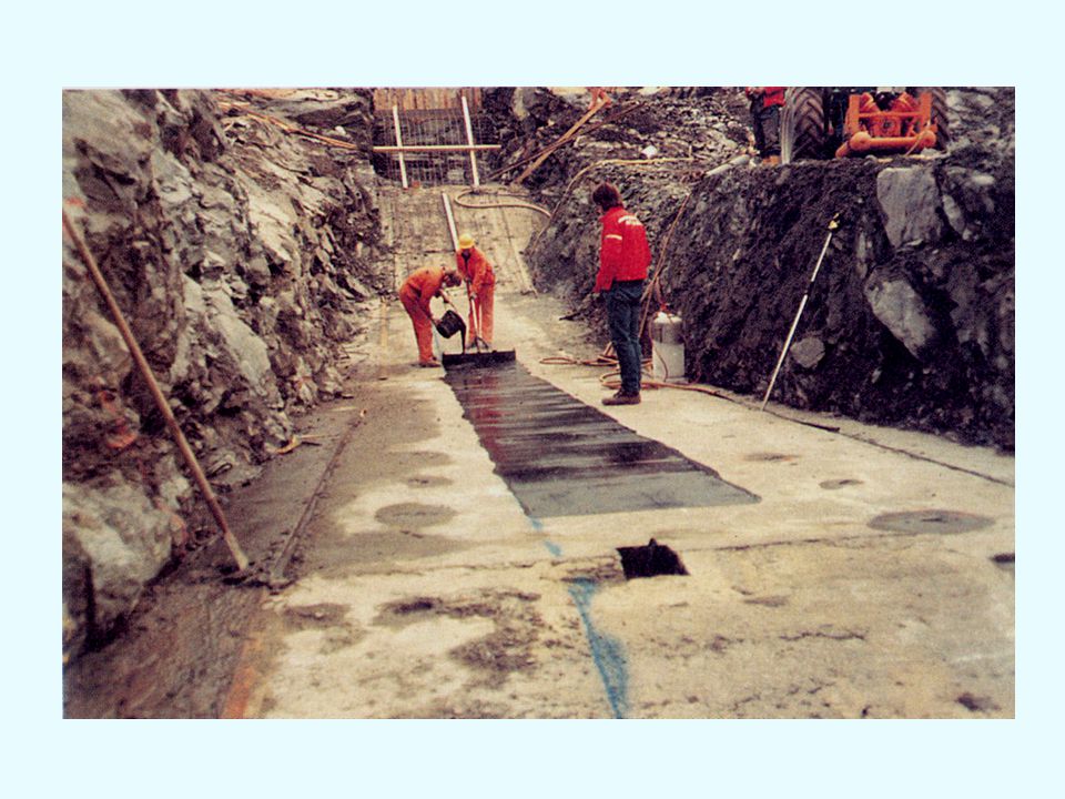
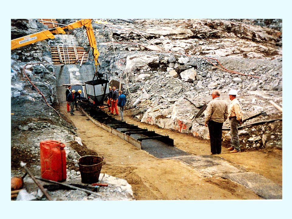
Preparation of concrete plinth (placing mastic)
")
33
Hand placement of first layers

34
Machine placement starts

35
Test strip on site prior to core construction

36
Compaction with 3 rollers

38
Field samples (0.5 m long) drilled out of dam core (no interface can be detected between layers)
 drilled out of dam core (no interface can be detected between layers)")
39
Cutting field core into 5 test pieces

40
Controlling field porosity

41
Field control laboratory

42
Field laboratory testing of mix from plant and of samples drilled out of the core

43
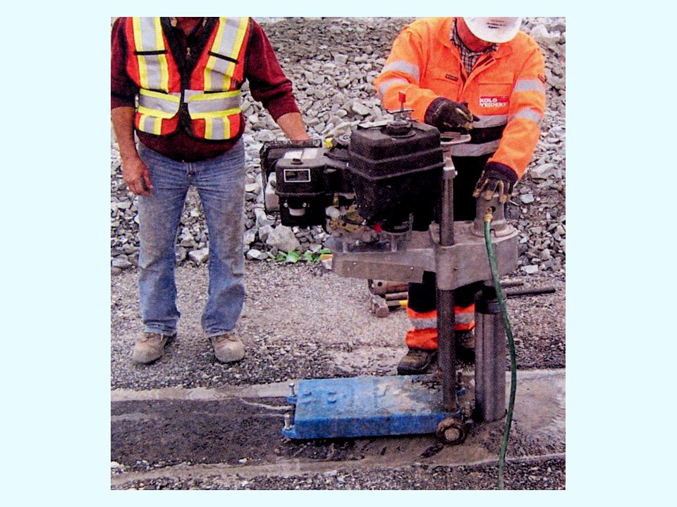
Porosity control without sampling

46
Excavated core from field test strip

47
Demonstration of core flexibility in test section

48
Demonstration of core flexibility (cont’d)
")
49
Effect of laboratory method of compaction on resulting stress-strain properties of asphalt
Triaxial results from laboratory prepared and field core specimens with the same air porosity have been compared. Differences in behaviour must be considered: - if stress–strain design requirements (compression modulus, degree of shear dilation and ductility) are based on test results from laboratory prepared specimens; - and if finite element analyses are used to predict or back-analyse core behaviour.
 are based on test results from laboratory prepared specimens; - and if finite element analyses are used to predict or back-analyse core behaviour.")
50
Effect of laboratory compaction procedure (how to best simulate field compaction in the lab.)
")
51
Storglomvatn Dam near completion (125m)
")
52
Zoning of Storglomvatn Dam (125 m)
1. Asphalt core 2. Transition (0-60 mm) 3.Transition (0-150 mm) 4a. Quarried rockfill (0-500 mm) 4b. Quarried rockfill ( mm) 5. Slope protection (blocks, min.0.5 m3) 6.Crown cap (blocks) 7. Toe drain (blocks, min. 0.5 m3) 8. Concrete plinth (sill) for core
 3.Transition (0-150 mm) 4a. Quarried rockfill (0-500 mm) 4b. Quarried rockfill ( mm) 5. Slope protection (blocks, min.0.5 m3) 6.Crown cap (blocks) 7. Toe drain (blocks, min. 0.5 m3) 8. Concrete plinth (sill) for core")
53
Yele Asphalt Core Dam (125 m, China)
Fig.5

54
Core-cutoff connection at Yele Dam, China

55
Special testing of core-plinth interface

57
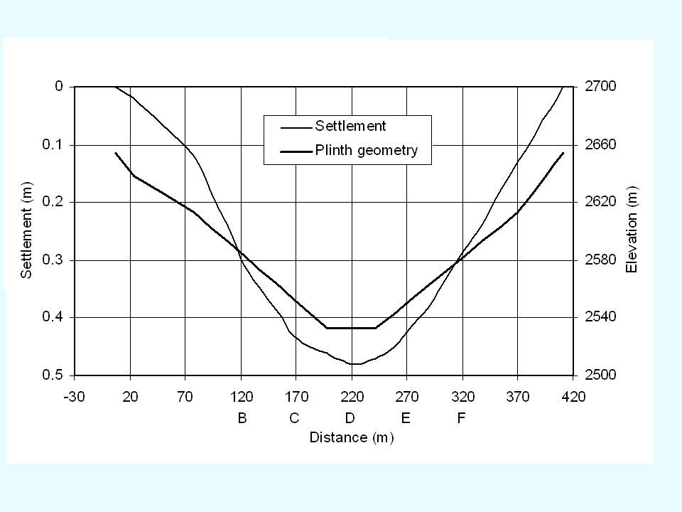
Back-calculated max.shear strain in core of Yele Dam

58
Optimum Design Considerations
Which embankment type is best suited for the local conditions, considering: - economy (construction and maintenance); - safety/reliability; - impact on the environment. The local foundation/geologic conditions will have significant impact on the choice of dam.
; - safety/reliability; - impact on the environment. The local foundation/geologic conditions will have significant impact on the choice of dam.")
59
Different embankment dam designs:
- earth core embankment dam (ECED) - asphalt core embankment dam (ACED) - concrete faced rockfill or gravel dam (CFRD) - geomembrane faced embankment dam (GFED) - faced hardfill dam (FHD or CSGD) Recent comparisons among alternatives show the ACED to be very competitive.
 - asphalt core embankment dam (ACED) - concrete faced rockfill or gravel dam (CFRD) - geomembrane faced embankment dam (GFED) - faced hardfill dam (FHD or CSGD) Recent comparisons among alternatives show the ACED to be very competitive.")
60
Asphalt concrete core - Simple and robust construction method;
- Asphalt concrete is a flexible and ductile material with viscoelastic-plastic properties (a “forgiving” material); - No core erosion; therefore no strict filter criteria; - Core adjusts to dam and foundation deformations; - Earthquake resistant; no deterioration of properties; - Self-healing (self-sealing) of any cracks; - Asphalt mix may be ”tailored” to satisfy special design requirements; - Can resist overtopping erosion during construction;
; - No core erosion; therefore no strict filter criteria; - Core adjusts to dam and foundation deformations; - Earthquake resistant; no deterioration of properties; - Self-healing (self-sealing) of any cracks; - Asphalt mix may be tailored to satisfy special design requirements; - Can resist overtopping erosion during construction;")
61
Thank you for your attention

Similar presentations


, Inc. September 2005 1 Canatuan Tailings Management Completion of Stage 1 Tailings Management Facilties Gossan Dam and.>")

>")


