Download presentation
Presentation is loading. Please wait.

1
Some Features of the European Norm for Cold-Formed Steel Design in comparison with the AISI Specification S. Ádány*, B. Schafer** *Budapest University of Technology and Economics **Johns Hopkins University

2
Outline Introduction Some features of cold-formed EC3 –Materials –Geometry –Local and distortional buckling –Member resistance –Design assisted by testing –Beams restrained by sheeting Numerical example

3
The Eurocodes Eurocode 0 (EN 1990) – Basis of the design Eurocode 1 (EN1991) – Actions (loads) Eurocode 2 (EN 1992) – Concrete structures Eurocode 3 (EN 1993) – Steel structures Eurocode 4 (EN 1994) – Composite (steel/concrete) str. … Note: ENV, prEN – certain preliminary versions

4
Eurocode 3 Part 1.1 – General rules Part 1.2 – Fire design Part 1.3 – Cold-formed steel Part 1.5 – Plated structures … Part 2 – Steel bridges …

5
Some comments on Eurocodes Not ready - some parts exist only in a very first draft version Continuously changing Flexible – „everything is allowed if the safety is OK” National Application Document (NAD) can modify almost everything
 can modify almost everything")
6
Principle of verifications Limit state design: Partial safety factor for the resistance: M Partial safety factor for the loads: G, Q Combination factor:

7
Basic notations Design value of resistance – subscript „Rd” Design value of actions – subscript „Ed” Yield strength: f y Slenderness: Reduction factor for buckling:

8
Scope of EC3 Part 1.3 Cold-formed profiled sheeting Cold-formed beams / columns Thickness: 0.45 mm ≤ t cor ≤ 15 mm (can be further limited by NADs)
")
9
Materials 60+ standardized steel material Yield strength: 220 – 700 MPa (32 – 101 ksi) According to EN and ISO standards Restrictions may apply for higher strength materials Other materials are allowed Requirements for other mats. are given

10
Hardening due to cold-forming Basic yield strength (f yb ) average yield strength (f ya ) To be applied for the whole section For fully effective sections, only The formula:
 average yield strength (f ya ) To be applied for the whole section For fully effective sections, only The formula:")
11
Rounded corners In general: fictitious plane elements are introduced Upper limit: –r ≥ 0.04tE/f y test is necessary Lower (optional) limit: –r ≤ 5t and r ≤ 0.1b p the effect can be neglected
 limit: –r ≤ 5t and r ≤ 0.1b p the effect can be neglected")
12
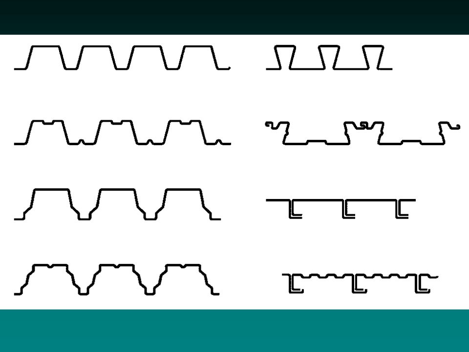
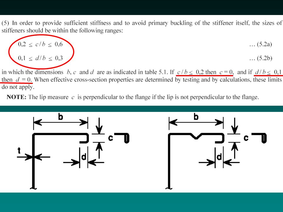
Geometrical limits b/t ratios, similar to AISI Spec. + limit for web inclination + limit for edge stiffeners

13
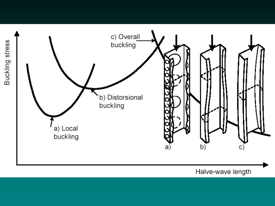
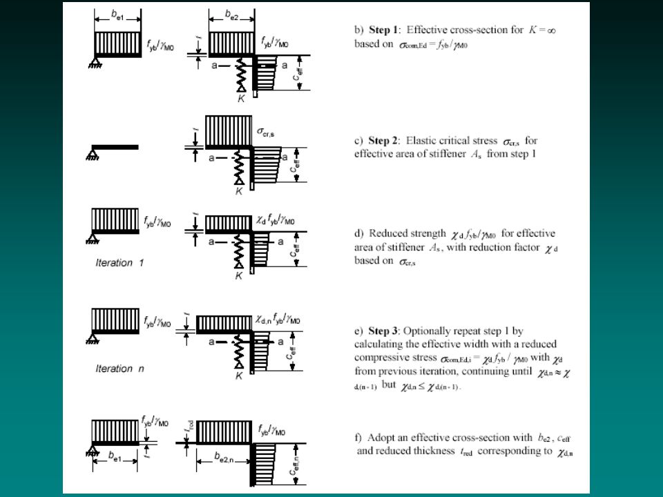
Buckling - general procedure 1.critical stress calculation (in function of half-wave length) 2.identification of buckling modes 3.calculation of effective widths based on the minimum local buckling stress 4.calculation of reduced thickness based on distortional buckling stress 5.calculation of reduction factor for overall buckling resistance based on effective cross-section
 2.identification of buckling modes 3.calculation of effective widths based on the minimum local buckling stress 4.calculation of reduced thickness based on distortional buckling stress 5.calculation of reduction factor for overall buckling resistance based on effective cross-section")
14
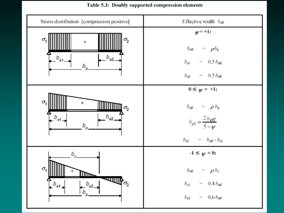
Local buckling Effective width approach Effective width: similar to Winter formula, but modified –for outstand elements –for stress gradient Effective sections:

15
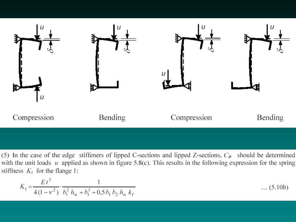
Distortional buckling Reduced thickness is determined for the stiffeners (or other distorted parts) For C/Z sections: hand method is given For other sections: numerical method is necessary Effective widths must be calculated prior to reduced thickness !
 For C/Z sections: hand method is given For other sections: numerical method is necessary Effective widths must be calculated prior to reduced thickness !")
16
Distort. buckl. – C/Z sections The basic model: Equivalent spring stiffness is given only for C/Z sections: Dist. buckl. stress critical stress of a bar on elastic foundation Reduction factor for the stiffener: Iteration for the thickness is necessary

17
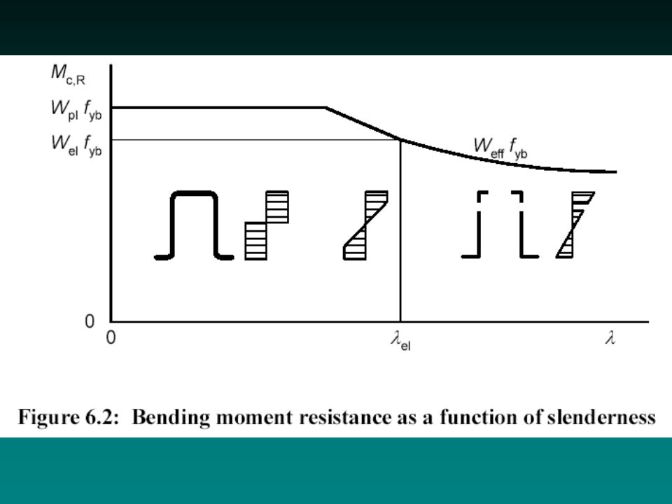
If the cross-section is not fully effective: If the cross-section is fully effective: If fully effective, + uniaxial bending about principal axis, + no torsion, + no any of torsional buckling, + web inclination is less than 30°: Bending moment resistance elastic resistance elastic resistance with hardening partial or full plastic resistance

18
Bending moment resistance If first yielding is in the tension flange: Bending moment redistribution is allowed. Effect of shear lag must be considered. (only a reference is given) partial plastic resistance
 partial plastic resistance.")
19
Torsion must be considered: – from St Venant torsion – and from warping No formulae given how to calculate stresses from torsion. Stresses from torsion must be summarized with stresses from other actions. Hardening effect can be considered. For shear, torsion: gross cross-section For normal force, bending moments: effective section Torsional moment resistance

20
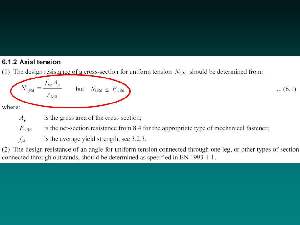
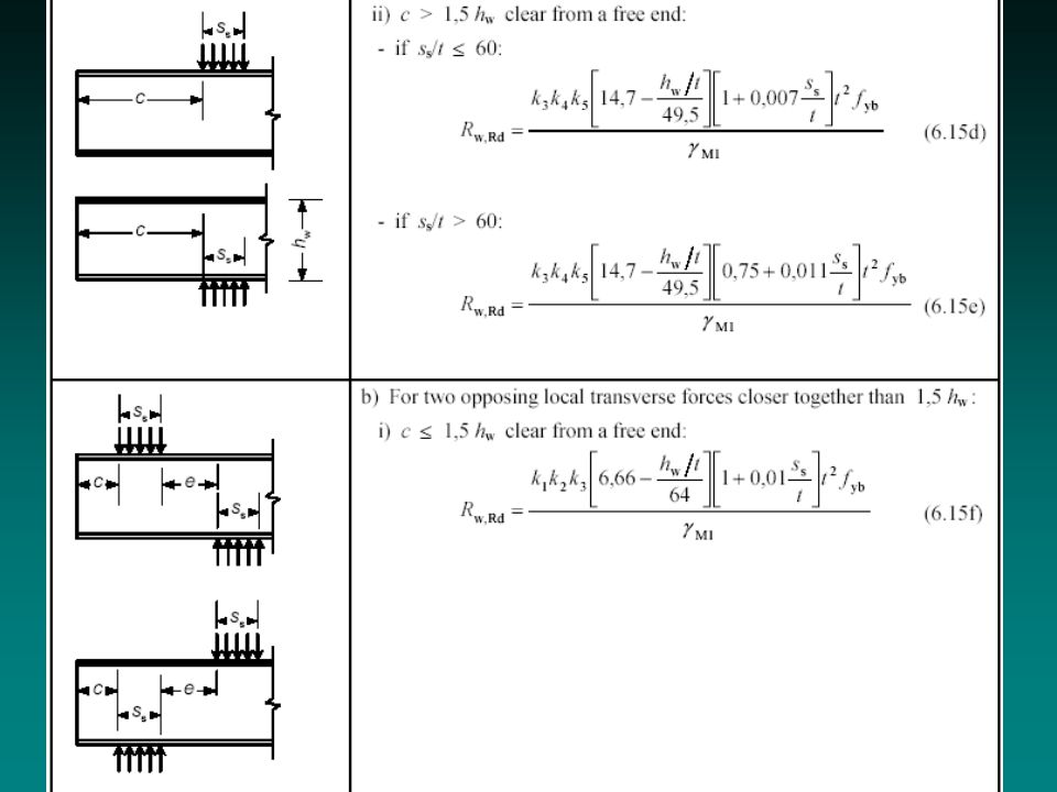
Tension: increased yield strength (f ya ) is used Compression: hardening may be considered shift of neutral axis must be considered Biaxial bending: linear interaction Shear: plastic and buckling resistances webs with longitudinal stiffeners are handled Crippling: detailed empirical formulae webs with longit. stiffeners are handled Interaction: shear+axial+bending is handled Other cross-sectional resistances

21
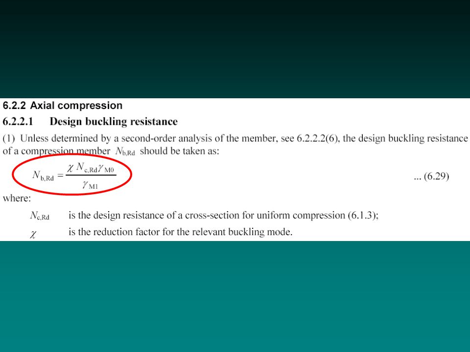
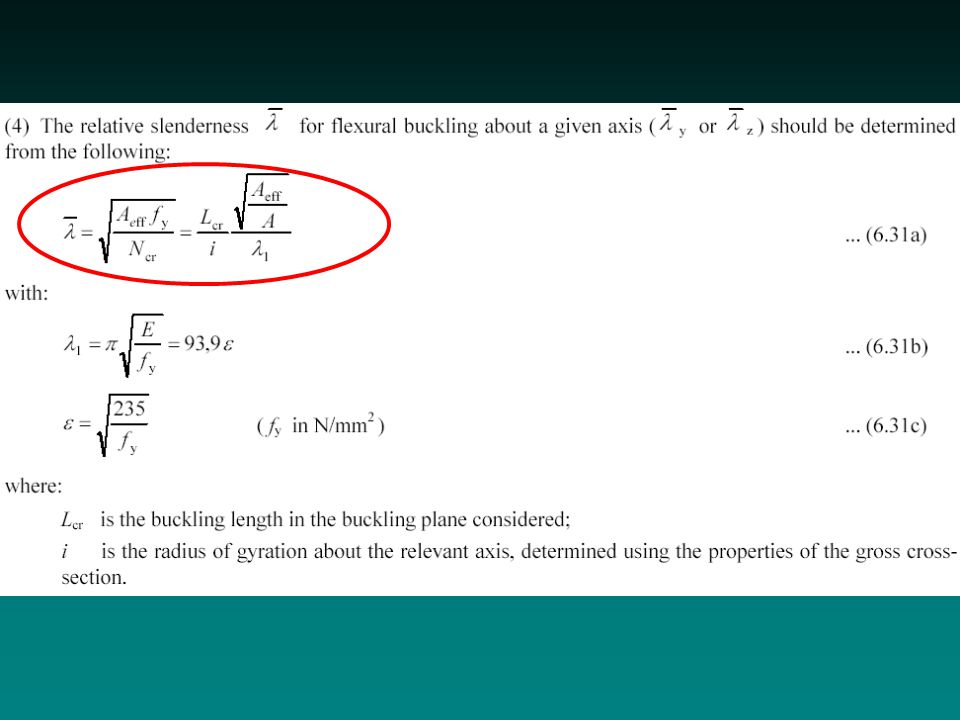
Buckling resistance is obtained from cross-sectional axial resistance, with a reduction factor ( ) For reduction: the European buckling curves are used Flexural buckling: –Resistance is calculated on the effective area –However, a reduced slenderness is used to calculate the reduction factor –f ya can be used for fully effective sections Buckling resistance for compression
 For reduction: the European buckling curves are used Flexural buckling: –Resistance is calculated on the effective area –However, a reduced slenderness is used to calculate the reduction factor –f ya can be used for fully effective sections Buckling resistance for compression")
22
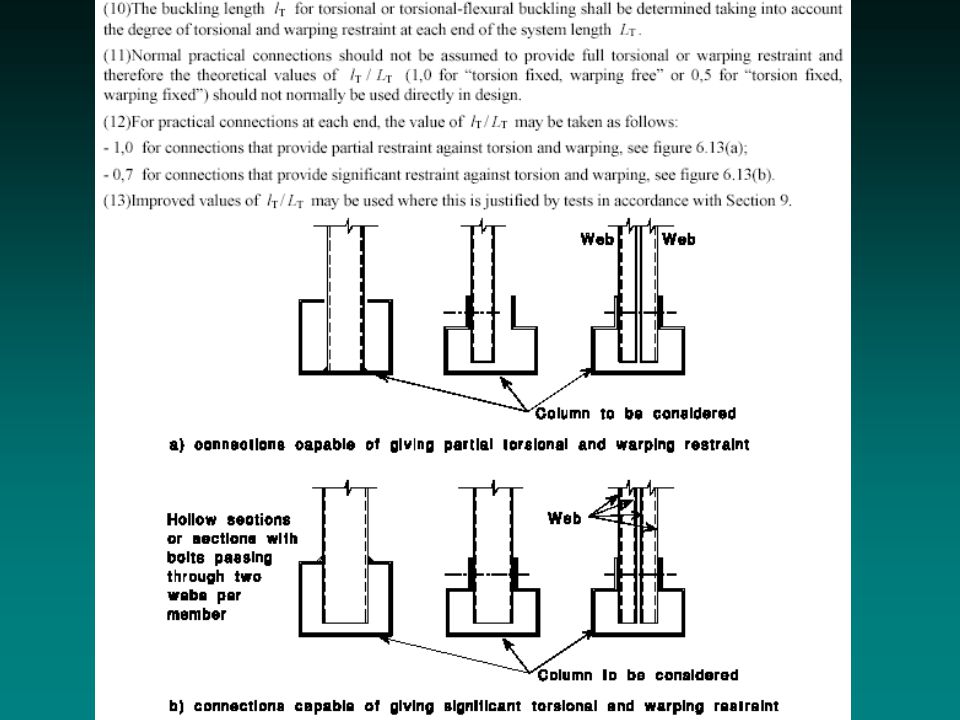
Torsional and torsional-flexural buckling: –basically the same as flexural buckling –numerical methods for calculation of critical force is allowed with the gross cross-section –guidance for end-conditions is given for some practical cases Buckling res. for comp. - torsion

23
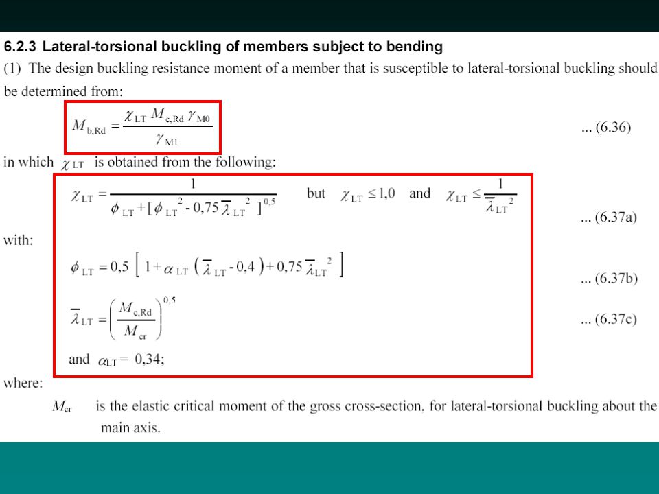
The given method can only be used: –for practically rigid cross-sections –if no significant angle between principal axes of gross and effective cross-sections Buckling resistance is obtained from cross-sectional bending resistance, with a reduction factor ( LT ) For reduction: a special LT buckling curve is used Resistance is calculated on the effective area However, a reduced slenderness is used to calculate the reduction factor f ya can be used for fully effective sections Buckling resistance for bending
 For reduction: a special LT buckling curve is used Resistance is calculated on the effective area However, a reduced slenderness is used to calculate the reduction factor f ya can be used for fully effective sections Buckling resistance for bending")
24
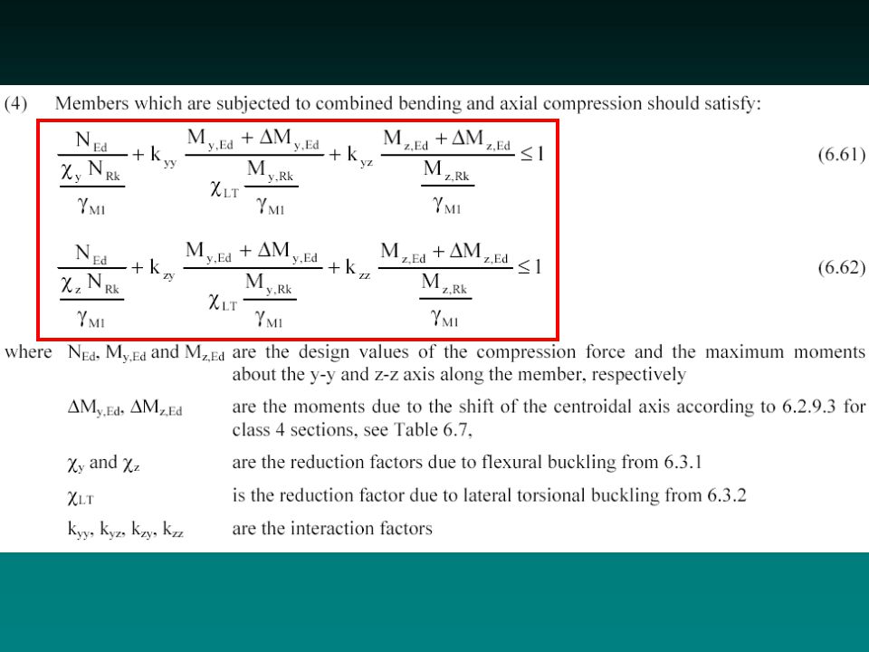
Second-order moments may be necessary to consider Interaction for double symmetrical cross-sections: –reference to Part 1.1 – two methods („German” vs. „French”) Interaction for other cross-sections Buckling res. for bending – contnd.
 Interaction for other cross-sections Buckling res. for bending – contnd..")
25
Relevant norms: –EN 1990 (Basis of design) –EN 1993-1-1 (General rules for steel) –EN 1993-1-3 (Cold-formed) Only guidance is given, limit values (deflection, etc) must be agreed with the client For cold-formed: –Fictitious moment of inertia is proposed –Influence of slip must be considered Serviceability limit states
 –EN (General rules for steel) –EN (Cold-formed) Only guidance is given, limit values (deflection, etc) must be agreed with the client For cold-formed: –Fictitious moment of inertia is proposed –Influence of slip must be considered Serviceability limit states")
26
Long list of principles are given: –planning, execution, evaluation and documentation Several specific tests are described –Tests on profiled sheets (single-span, double-span, internal support, end-support tests) –Tests on beams/columns (stub column, member buckling, cross-s. tension, c.s. bending) –Tests on assemblages / structures (acceptance, strength, prototype failure, calibration) –Tests on torsionally restrained beams (…, …) Design assisted by test
 –Tests on assemblages / structures (acceptance, strength, prototype failure, calibration) –Tests on torsionally restrained beams (…, …) Design assisted by test.")
27
Combination of tests and mathematical models is allowed Evaluation of test results: Measured data Adjusted results Mean value Characteristic value Design value Design assisted by test – contnd.

28
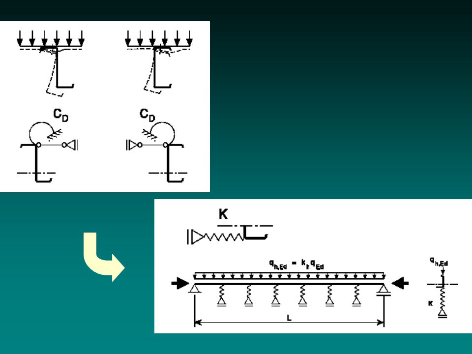
Basic model: Verification: –Normal force + „vertical” bending + lateral bending –Buckling Simplified method is also available Beams restrained by sheeting

29
A numerical example has been worked out Local and distortional buckling of Z/C beams Numerical example EXAMPLE

30
Thank you.

46
elastic plastic elastic with hardening To Figure

51
elastic plastic

53
shear buckling shear yielding

Similar presentations


 CE 408 ( 2 – 3 – 3 ) Semester 062>")