Download presentation
Presentation is loading. Please wait.

1
California Maritime Academy EPO 220 Diesel Engineering I Fuel Injection & Combustion Chamber Design Material Compiled by Robert Jackson

2
Diesel Engine Combustion Chambers Combustion chambers are designed to promote air turbulence which helps atomize the fuel in preparation for combustion. open Modern diesel engines typically utilize an open type combustion chamber. Though not commonly used today, the following chamber designs were utilized in the past to promote complete combustion: Turbulence Chambers Precombustion Chambers Energy Cell or Air Cell Chambers

3
Air Turbulence in the Combustion Chamber A- Intake Stroke; B-Compression Stroke; C-Power Stroke; Exhaust Stroke

4
Diesel Engine With Open Combustion Chamber

5
Typical Open Combustion Chamber Design

6
Hemispherical Type Open Combustion Chamber

7
M Type Open Combustion Chamber

8
Precombustion Chamber

9
The precombustion chamber is connected to the piston clearance volume by one or more passages. This chamber may be located in the head or cylinder wall. A precombustion chamber will hold 25 to 40 percent of the total clearance volume. Because of the larger surface area of the combustion chamber, heat losses are increased and thermal efficiency decreases. The precombustion chamber promotes smooth combustion and improves engine performance at low loads.

10
Mercedes Diesel With Precombustion Chamber & Glow Plug

11
Removable Injector plus Precombustion Chamber Combination (Caterpillar Tractor Co.)
")
12
SEMT Pielstick Variable Geometry Combustion Chamber

13
Turbulence Chamber

14
The turbulence chamber is very similar in design to the precombustion chamber. The principal difference between the two designs is the amount of chamber volume compared to the clearance volume of the main combustion chamber. Engines utilizing turbulence chambers have very small clearance volumes. When the piston reaches TDC virtually all of the available air has been compressed in the turbulence chamber. The chambers are usually spherical in shape and are incorporated into either the head or cylinder. The opening through which the air must pass becomes smaller as the piston reaches the top of the stroke, thereby increasing the velocity of the air in the chamber.

15
Waukesha Engine Turbulence Chamber

16
Lanova Energy Cell

17
The Lanova Energy Cell The energy cell is a combination of the precombustion chamber and turbulence chamber designs. The Lanova system has two rounded combustion spaces shaped like a figure 8. The fuel is injected in a pencil stream, passing directly across the narrow throat of the combustion chamber so most of the fuel enters the energy cell. Most of the fuel entering the energy cell is trapped in the small inner cell, but a small portion passes into the outer cell where it meets with a sufficient quantity of super-heated air to explode violently.

18
Combustion Sequence in the Lanova Energy Cell System The nozzle injects fuel in a pencil stream which penetrates into the energy cell. Partial combustion takes place inside the energy cell radically raising cell pressure. High pressure gasses exiting the energy cell through the venturi throat cause high turbulence levels in the main combustion chamber promoting good combustion.

19
Pintle & Hole Type Fuel Injector Nozzle

20
Operation Of Fuel Injection Nozzle

22
Angular Difference Between Needle Face & Injector Seat

23
Fuel Injectors

24
Fuel Line Pressure (lower line) & Needle Lift Diagrams a)At high load b)At low load
 & Needle Lift Diagrams a)At high load b)At low load")
25
Injector Nozzle Tip for the Mak

26
Mak Fuel Injector With Oil Cooling

27
Sulzer RND-M Injector Non-Recirculating Type, Water Cooled

28
Fuel Injector Hold Down Bolt Tensioning Washer Disk Stack

29
Sulzer Fuel Injectors

30
Low Sac Volume Fuel Injection Nozzle Tip

31
Injector Tip Advances To Minimize Sac Volume

32
Port & Helix High-Pressure Fuel Pump

33
Effective Stroke of the Port & Helix Pump

34
Port & Helix High-Pressure Fuel Pump Illustration showing pump plunger, barrel, delivery valve, & control rack for adjustment of pump effective stroke

35
Exploded View of the Port & Helix Fuel Pump

36
High-Pressure Fuel Pump & Camshaft Follower For Mak 6M 322 Diesel Engine

37
High-Pressure Fuel Pump Timing

38
Balance Delivery Valve Utilized on Mak 6M 322 Diesel Engine

40
MAN B&W K98MC Slow-Speed Crosshead Diesel Engine Bore 980mm Stroke 2660mm 94 Rpm Maximum 6 to 12 Cylinders 5,720 kW Per Cylinder 12 Cylinder Engine Produces 68,640 kW (93,360 BHP)
")
41
MAN B&W Slow-Speed Diesel Engine High-Pressure Fuel Pump

42
MAN B&W Fuel Pumps

43
B&W Slow-Speed Diesel Engine High-Pressure Fuel Pump With Variable Injection Timing

44
B&W High-Pressure Fuel Pump

46
Fuel Pump Shock Absorber

48
The Modern Slow Speed Diesel Engine

49
Sulzer RTA84C Diesel Engine

50
Sulzer Fuel Pump Placement

52
Sulzer RTA84T High-Pressure Fuel Pump

53
RTA Camshaft, Valve Actuators, & High Pressure Fuel Pumps

54
Sulzer Valve Controlled High-Pressure Fuel Pump

56
Spill Valve Cut-away Illustration

57
Sulzer High-Pressure Fuel Pump Block 1Cover 2Cylinder 3Piston 4Slide Ring 5Viton-ring 6Conical Clamp Ring 7Spring 8Spring Plate 9Spindle 10Guide Bush 11Rubber “O” Ring 12Suction Valve 13Rubber “O” Ring 14Yoke DDelivery Valve USpill Valve SSuction Valve

58
D –Delivery Valve U -Spill Valve S -Suction Valve 10 –Connecting piece for high pressure fuel pipe 11 –Tension Bolt 30 –Cover for suction & Spill Valve 31 –Rubber Ring 32 –Relief Valve 33 –Guide Bush 34 –Push Rod 35 –Spring 36 –Locking Wire 37 –Pressing Nipple

59
Fuel Pump Effective Stroke Without Variable Injection Timing

60
Sulzer Safety Cut-Out Device

61
Constant Volume or “OTTO” Cycle

62
Dual Cycle

63
The Stroke Based Indicator Card

64
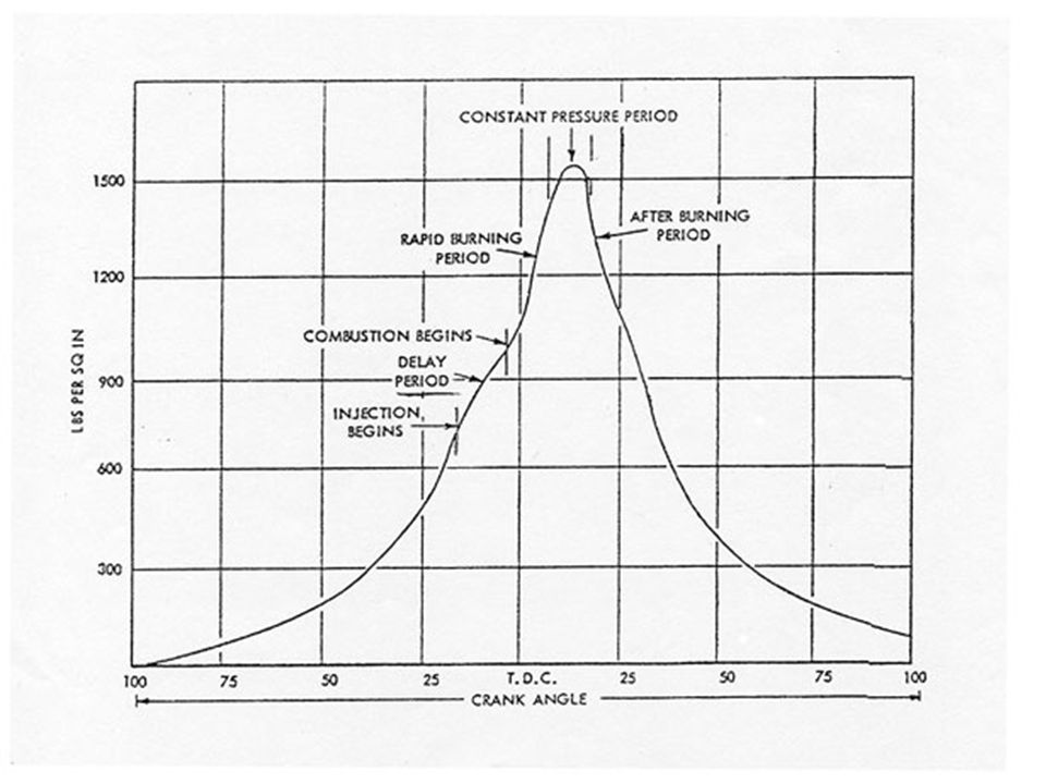
Typical Indicator Diagram (crank-angle based)
")
66
Indicator Card Showing Retarded Ignition Due to Low Quality Fuel

67
Example of Retarded Ignition

68
Variable Injection Timing Characteristics

69
Fuel Pump Effective Stroke With Variable Injection Timing

70
Fuel Pump Linkage

71
Port & Helix High-Pressure Fuel Pump With Variable Injection Timing

72
MAN B&W Fuel Pumps

73
MAN B&W High-Pressure Fuel Pump

75
MAN B&W Medium Speed Diesel Engine L32/40

76
Variable Injection Timing Used On L32/40 Medium-Speed Diesel Engine

77
Wartsila Split High-Pressure Fuel Pump

78
Wartsila Split Pump Operation

79
For description of pump operation see “Wartsila 64 Technical Review” pp 14

80
Typical Heavy Fuel Oil System

81
Nozzle Tip Fuel Circulation

82
Nozzle Fuel Circulation

83
Sulzer Circulating Type Injectors

84
B&W Circulating Type Fuel Injector

85
B&W Cylinder Cover Showing High-Pressure Pipes & Fuel Injectors

87
Unit Type Fuel Injector

89
Distributor Type Fuel Injector System

Similar presentations


 Engine Lab Instructor: M>")
 Patel Vidhi A.>")
 engine To determine the effect of load variation at constant speed.>")


