Download presentation
Presentation is loading. Please wait.

1
Anchorage and Development Length

3
Development Length - Tension Where, α = reinforcement location factor β = reinforcement coating factor γ = reinforcement size factor λ = lightweight aggregate concrete factor K t r = 0 as a design simplification c = spacing or cover dimension for further information and values, see page 31a, notes transverse reinforcement index Excess reinforcement: l d may also be modified by (A s required/ A s provided)
")
4
Development Length - Compression l dc may be modified by the following: Reinforcement in excess of that required by analysis ………..A’ s required/A’ s provided Spirally reinforced column bars and bars surrounded by closely spaced ties………..0.75

5
Standard Hooks When sufficient embedment length is not available for tensile reinforcing bars, they may be bent into the shape of a hook (hooks are not effective in compression). basic hook development length for uncoated rebar in normal weight concrete: l dh ≥ l hb (modification factors) ≥ 8 db ≥ 6 in. Modification factors: For side cover ≥ 2 ½ in. normal to plane of hook, and for 90° hook with cover on extension beyond hook ≥ 2 in. …………………..0.7 If the hook is enclosed vertically or horizontally within ties space ≤ 3 d b along the full length l dh ……………………………………….0.8 When anchorage for full development is not specifically required, and there is excess reinforcement…………………A s required/A s provided
 ≥ 8 db ≥ 6 in. Modification factors: For side cover ≥ 2 ½ in. normal to plane of hook, and for 90° hook with cover on extension beyond hook ≥ 2 in. …………………..0.7 If the hook is enclosed vertically or horizontally within ties space ≤ 3 d b along the full length l dh ……………………………………….0.8 When anchorage for full development is not specifically required, and there is excess reinforcement…………………A s required/A s provided.")
6
Standard Hooks

7
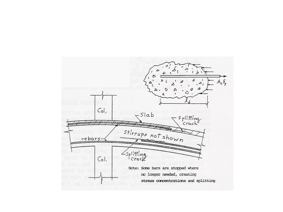
Critical points, c, occur at points of maximum moment. All reinforcement must be anchored distances l d or l dh on both sides of these points. Critical points, x, are formed in bars that continue past bars that are stopped. The points x are to be taken as the theoretical stopping point of bars that actually are stopped further along the beam in accord with Code requirements. The continuing bars must extend ≥ l d beyond the points x. The bars being stopped must continue the greater of d, 12 d b or, when the last ⅓ of top reinforcement is being stopped, l n /16 beyond the point where they are theoretically no longer needed.

8
Zero Positive Moment Locations At points of zero positive moment a minimum A s is required: l a = greater of d or 12 d b

9
Reinforcement Stopped in a Tension Zone Flexural reinforcement may not be stopped in a tension zone unless one of the following conditions is satisfied: a.Shear at the cutoff point is ≤ ⅔Ф(V c +V s ) b.Excess stirrups are provided form the cutoff point for a distance = 3/4d past it. (see notes p. 33) c.The continuing reinforcement provides double the As required at the cutoff point and Vu ≤ ¾Ф(V c +V s )
 c.The continuing reinforcement provides double the As required at the cutoff point and Vu ≤ ¾Ф(V c +V s ).")
10
Maximum Moment Diagrams

11
Reinforcement Layout WWF 3 #5 bars 50” 97” 37”8.3” 2#5 bars 60” 3 #5 bars

Similar presentations


: A rectangular beam has the dimensions shown in Figure 4.12.a and is loaded with a 40 ton concentrated.>")


 Superstructure – Reinforced Concrete Bridges>")
