Download presentation
Presentation is loading. Please wait.

1
Orto Tech Design Ltd. SYSTEM FOR AXIAL EXTERNAL FIXATION "NESTOROV"

2
UNDERLYING OWN PATENTS Title page of the patent 100327 / 31.01.96 ‘External fixator’ Title page of the patent 100328 / 31.01.96 ‘Adjustable connection between elements for external fixation ’

3
“Universal, extremely simple and incredibly strong... This is the “Kalashnikov” in the external fixation.” prof. Kukuruz J. S. Chief of Department of Traumatology of the Institute of Accident Medicine, Kiev, Ukraine; Former main front traumatologist in Afghanistan

4
PURPOSE System for axial external fixation is designed for orthopaedics and thraumatic surgery and is applied in treatment of long tubular bones. It represents a system of modules which when mounted form a multi - functional external construction. By means of this system, repositioning of bone fragments can be achieved; moreover, bone fragments can be immobilized in that position for a certain period by means of building an external supporting construction connected with the screws implanted in the bones.

5
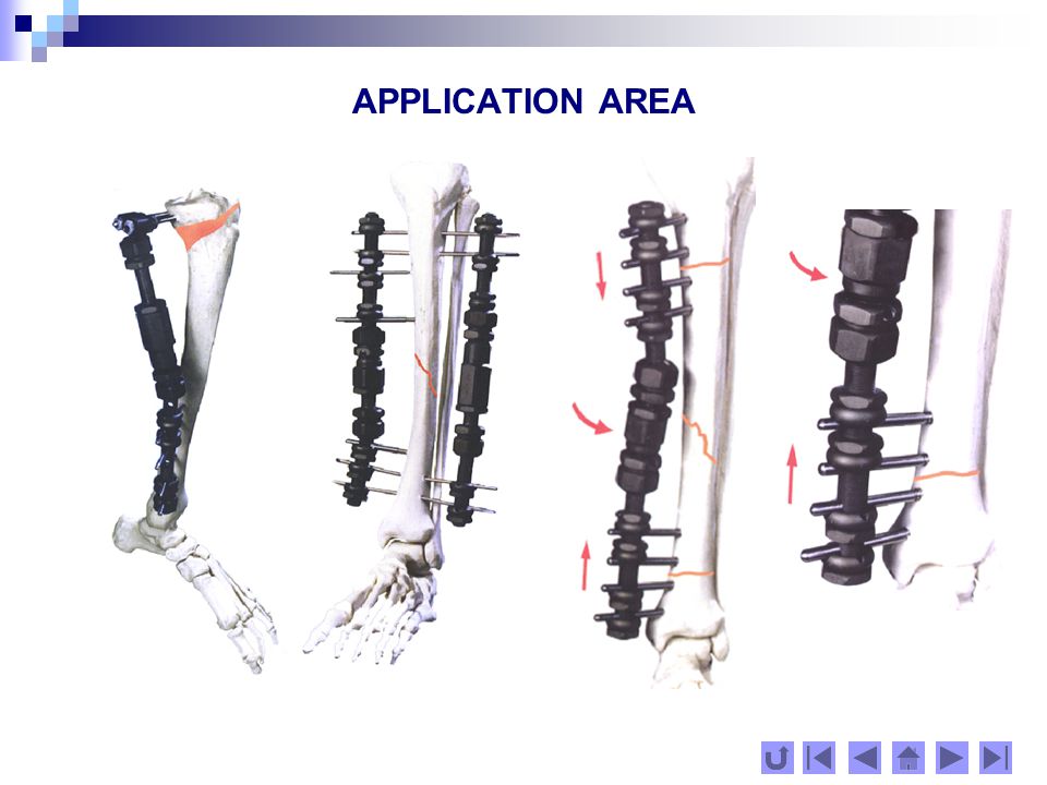
APPLICATION AREA The system for external fixation "Nestorov" could be applied in the following cases: open and closed fractures in different places; single and multiplex fractures; in-joint and out-joint fractures; fractures with infections; unhealed fractures and complex joints /pseudoarthrosis/; shortened extremities.

6
APPLICATION AREA

8
CONTENT The system for external fixation "Nestorov" includes: set of different /in construction/ metal items (fixators), which could be joined to each other and form an external frame with multiple functions and different strength, in dependence of the place and purpose. metal screws, different in diameter and length, which are designed for implantation in bones. instruments, necessary for working with the system.

9
PURPOSE OF THE MAIN MODULES The metal frame of the external fixator consists of the following main modules: screw holder– fastens the implant screws, allowing compression or distraction of bone fragments thanks to the fixation of the screws in oblong holes compressor-distractor – connects two screw carriers by means of spherical links, ensuring compression or distraction of bone fragments. module with 2 spherical beds – connects two screw holders by means of spherical links module transferring 90 O – used in fixators designed for treatment of supracondilar fractures; module transferring 135 O - used in fixators designed for fractures of the neck of the femoral capitellum

10
PRINCIPLE OF ACTION OF THE MECHANISMS Consists of a nut (1), mobile connected with a pressing bush (2), moving linear along the threading stem (3) with cross holes (4) for the screws, finishing with unificated ball-and- socket joint. The screw (5) mounted in the bone is pressed to the bottom of the elongated hole by screwing the nut (1), as the positioned at the very beginning of the hole screw moves linear along the screw holder axis from 2 to 5 mm. MECHANISM, FIXING THE SCREWS 1 2 3 4 5 5
 mounted in the bone is pressed to the bottom of the elongated hole by screwing the nut (1), as the positioned at the very beginning of the hole screw moves linear along the screw holder axis from 2 to 5 mm. MECHANISM, FIXING THE SCREWS")
11
PRINCIPLE OF ACTION OF THE MECHANISMS The simpliness of this decision creates some interesting new possibilities: Reversing the direction of the bush movement creates conditions for compresson or distraction of the fixing screws in the screw holder. In this way, monofixators for multifragment fractures can be synthesized. Possibilities for independent assembly of the screws with different diameters /from 3 to 6 mm/ to all levels of the screw holder. Conditions for dosing the elasticity of the fixation at the very beginning of the treatment. Possibilities for combination of the screw holders /with 2 to 10 holes/ in order to achieve an individual strong frame, allowing screw tightening as near to the fracture line as possible. MECHANISM, FIXING THE SCREWS

12
PRINCIPLE OF ACTION OF THE MECHANISMS The ball consists of two parts: a solid polished one (4) made of stainless alloy, and a front soft one (3) - of aluminium. After achieving a good fragment reposition, the nut with the spherical interior plane (5) is screwed and presses the ball to the spherical bed (2). A screw (1) with a sharp conic point is screwed for additional interlock of the mechanism. This link enables the assembly of a wide range of apparatus. The assembled modules can be turned in relation to each other at an angle of 20 0 in all spatial positions. UNIFICATED BALL AND SOCKET JOINT 13 4 25
 is screwed and presses the ball to the spherical bed (2). A screw (1) with a sharp conic point is screwed for additional interlock of the mechanism. This link enables the assembly of a wide range of apparatus. The assembled modules can be turned in relation to each other at an angle of 20 0 in all spatial positions. UNIFICATED BALL AND SOCKET JOINT")
13
PRINCIPLE OF ACTION OF THE MECHANISMS UNIFICATED BALL AND SOCKET JOINT

14
PRINCIPLE OF ACTION OF THE MECHANISMS The mechanism comprises a threaded guide (5) ending with an element of the ball-and- socket joint (8) and having a rectilinear groove (6) along the threaded stem. The envelope (3) is screwed on the guide (5), both performing linear movement axially together with the follower (2). The turning of the follower (2) in relation to the guide (5) is blocked by the pellets (7), which move along the grooves (6) of the на guide (5). The nut (4) is intended to block the follower (2). This mechanism ensures stable and smooth compression-distraction, combined with reliable blocking in the desired place. COMPRESSION-DISTRACTION MECHANISM 1 3 4 2 5 76 8
 is screwed on the guide (5), both performing linear movement axially together with the follower (2). The turning of the follower (2) in relation to the guide (5) is blocked by the pellets (7), which move along the grooves (6) of the на guide (5). The nut (4) is intended to block the follower (2). This mechanism ensures stable and smooth compression-distraction, combined with reliable blocking in the desired place. COMPRESSION-DISTRACTION MECHANISM")
15
PRINCIPLE OF ACTION OF THE MECHANISMS COMPRESSION-DISTRACTION MECHANISM

16
PRINCIPLE OF ACTION OF THE MECHANISMS The transferring modules have holes for the implant screws, their axes placed at an angle to the sphere axis. The holes are double conic, the bigger diameter turned outside. The screws used for these modules have threading on their stems. The screws are fastened in the holes by means of split conic bushes, screwed on the screw stem. When the bush is tightened, because of its conic shape, its segments are contracted, thus tightening the screw reliably. This construction allows adjustment of the screw position axially, ensuring precise repositioning of the bone fragments. MECHANISM OF TRANSFERRING MODULES

17
PRINCIPLE OF ACTION OF THE MECHANISMS MECHANISM OF TRANSFERRING MODULES

18
SCREW DESIGN Implant screws are combinations of a drill 1, screw tap 2 and screw 3. That allows screws to be fixed into the bone without preliminary preparation. At the beginning the screw is with an arc profile that slightly turns into cylindrical one. The threading of the screw is with a special self-locking profile that ensures the preservation of maximum osseous tissue. The end of the screw is with a triangular profile that allows fitting to a wrench with the same profile or to a three-jaw chuck. 123

19
ADVANTAGES Simple, reliable, light, versatile system, effective in healing of different types of displaced fractures Very easy to apply within a short operative period. Ensures hopeful fixation in fractures in reduction position. Adaptability – the spatial position of modules can easily be changed – axially and around the three axes of rotation. With this system one can achieve independent reposition of the fragments of the fracture and then fix firmly the attained good position of the fragments. Universal with respect to the implant screws – on each screw holder screws with different diameters can be mounted - from 3 up to 6 mm. Performs compression-distraction in two ways: through the compressor-distractor module and through the compression-distraction nuts of the screw holders which turns it into a monofixator for treatment of multiple fractures. Isolator property achieved by hard anodized coating with Al 2 O 3

20
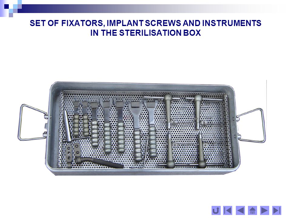
SET OF FIXATORS, IMPLANT SCREWS AND INSTRUMENTS IN THE STERILISATION BOX

23
EXTERNAL FIXATOR FOR UPPER EXTREMITY 1800100screw holder with 2 holes and 2 nuts 2800100-01screw holder with 3 holes and 2 nuts 3800100-02screw holder with 4 holes and 3 nuts 4800100-03screw holder with 5 holes and 3 nuts 5800100-04screw holder with 6 holes and 4 nuts 6800100-05screw holder with 7 holes and 4 nuts 7800100-06screw holder with 8 holes and 4 nuts 8804000compressor-distractor short 9804000-01 compressor-distractor long 10800900 module with 2 spherical beds 11801000module transferring 90 O 12801100 module transferring module transferring 135 O 1 2 3 4 5 6 7 8 9 10 11 1212

24
EXTERNAL FIXATOR FOR LOWER EXTREMITY 1 2 3 4 5 6 7 8 9 10 1112 1800200screw holder with 2 holes and 2 nuts 2800200-01screw holder with 3 holes and 2 nuts 3800200-02screw holder with 4 holes and 3 nuts 4800200-03screw holder with 5 holes and 3 nuts 5800200-04screw holder with 6 holes and 4 nuts 6800200-05screw holder with 7 holes and 4 nuts 7800200-06screw holder with 8 holes and 4 nuts 8800200-07screw holder with 9 holes and nuts 9800200-08screw holder with 10 holes and nuts 10804000-02 compressor-distractor short 11804000-03 compressor-distractor long 12800900module with 2 spherical beds 13801000-01 module transferring 90 O 14801100-01module transferring 135 O 1414 13

25
INSTRUMENTS 900100-05 wrench 12 900100-08 wrench 15 900100-10 wrench 19 900100-11 wrench 22 900100-13 wrench 27 905100screw spanner Ø3 905100-01screw spanner Ø4 905100-02screw spanner Ø5 905100-03screw spanner Ø6 920100guide with arm 900100-xx905100-xx 920100

26
INSTRUMENTS 901000barrel spanner 12 902200 screw spanner S 3.5 920300guide for transferring modules 909200spanner for trocars and protectors 922100protector short Ø3 922100-01protector short Ø4 922100-02protector short Ø5 922100-03protector short Ø6 922200protector long Ø3 922200-01protector long Ø4 922200-02protector long Ø5 922200-03protector long Ø6 923000trocar Ø3 923000-01 trocar Ø4 923000-02trocar Ø5 923000-03 trocar Ø6 901000 902200 920300 909200 923000-xx 922200-xx 922100-xx

27
SCREWS Note: In working with the system it is admissible to use implant screws and spokes of other systems and manufacturers, allowed for clinical use. cat. №Name 700200-02screw Ø4 L 080/20 700200-03screw Ø4 L 090/20 700200-04screw Ø4 L 100/25 700200-05screw Ø4 L 110/25 700400-01screw Ø5 L 090/30 700400-03screw Ø5 L 100/35 700400-05screw Ø5 L 110/35 700400-07screw Ø5 L 120/40 700500-03screw Ø6 L 100/35 700500-05screw Ø6 L 110/40 700500-07screw Ø6 L 120/40 700500-09screw Ø6 L 130/40

28
CANNULATED SCREWS Note: In working with the system it is admissible to use implant screws and spokes of other systems and manufacturers, allowed for clinical use. cat. №Name 700600-01Ø6 mm L 90/30 700600-03Ø6 mm L 100/35 700600-05Ø6 mm L 110/40 700600-07Ø6 mm L 120/40 700600-09Ø6 mm L 130/40 700600-11Ø6 mm L 140/40 700600-13Ø6 mm L 150/45 700600-15Ø6 mm L 160/50

29
SCREWS WITH THREADING AND 2 NUTS 701000-03screw Ø6 L 100/35 701000-05screw Ø6 L 110/40 701000-07screw Ø6 L 120/40 701000-09screw Ø6 L 130/40 701000-11screw Ø6 L 140/40 701000-13screw Ø6 L 150/45

31
APPLICATIONS ANTEBRACHIUM FRACTURES 800100 arm with 2 holes & 2 nuts2 804000 compressor-distractor short 1 700200-04 screw Ø4 L 100/254 800100arm with 2 holes & 2 nuts1 800100-02arm with 4 holes & 4 nuts1 804000compressor-distractor short1 700200-05 screw Ø4 L 110/256 800100-01 arm with 3 holes & 3 nuts2 804000compressor-distractor short1 700200-04 screw Ø4 L 100/256

32
APPLICATIONS HUMERUS FRACTURES 800100arm with 2 holes & 2 nuts1 800101 arm with 3 holes & 3 nuts1 804000 compressor-distractor short 1 700400-05 screw Ø5 L 110/355 800100 arm with 2 holes& 2 nuts1 800100-02 arm with 4 holes& 4 nuts1 804000 compressor-distractor short 1 700400-05 screw Ø5 L 110/356 800100-01 arm with 3 holes & 3 nuts2 804000 compressor-distractor short1 700400-05 screw Ø5 L 110/356

33
APPLICATIONS HUMERUS FRACTURES 800100 arm with 2 holes & 2 nuts1 804000 compressor-distractor short 1 801100 module transferring 1351 700400-07 screw Æ 5 L 120/402 701000-11 screw Æ 6 L 140/40 with 2nuts2 800100-01 arm with 3 holes & 3 nuts1 804000-01 compressor-distractor long1 801000 module transferring 901 700400-07 screw Æ 5 L 120/403 701000-07screw Æ 6 L 120/40 with 2 nuts2

34
APPLICATIONS TIBIA FRACTURES 800200-01 arm with 3 holes & 3 nuts2 804000-02 compressor-distractor short 1 700500-07 screw Æ 6 L 120/406 800200 arm with 2 holes & 2 nuts 1 804000-03 compressor-distractor short 1 801000-01 module transferring 901 700500-11 screw Æ 6 L 140/40 4 701000-15 screw Æ 6 L 160/45 with 2 nuts2 800200 arm with 2 holes & 2 nuts 1 800200-03 arm with 5 holes & 5 nuts1 804000-02 compressor-distractor short 1 700500-11 screw Æ 6 L 140/40 7

35
APPLICATIONS FEMUR FRACTURES 800200-01 arm with 3 holes & 3 nuts1 800200-03 arm with 5 holes & 5 nuts1 804000-02 compressor-distractor short 1 700500-14 screw Æ 6 L 160/458 800200-02 arm with 4 holes& 4 nuts 1 800200-03 arm with 5 holes & 5 nuts1 804000-03 compressor-distractor long 1 700500-14 screw Æ 6 L 160/45 9 800200-01 arm with 3 holes & 3 nuts1 800200-04 arm with 6 holes & 6 nuts1 804000-02 compressor-distractor short1 700500-14 screw Æ 6 L 160/45 9

36
APPLICATIONS FEMUR FRACTURES 00200-04 arm with 6 holes & 6 nuts1 800200-05 arm with 7 holes & 7 nuts1 804000-02 compressor-distractor short1 700500-14 screw Æ 6 L 160/4513 800200-02 arm with 4 holes & 4 nuts1 804000-03 compressor-distractor long 1 801100-02 module transferring1351 700500-11 screw Æ 6 L 140/40 4 701000-23 screw Æ 6 L 200/80 with 2 nuts3 800200-02arm with 4 holes & 4 nuts1 804000-03 compressor-distractor long1 801000-01module transferring 901 700500-11 screw Æ 6 L 140/40 4 701000-19screw Æ 6 L 180/60 with 2 nuts2

37
OPERATING MANUAL 1. Operation planning 2. Before the operation, concerning the plan, the orthopaedic surgeon chooses the necessary modules from the set and prepares them for sterilisation. 3. Sterilisation is done according to the instructions: Sterilisation approach ImplantsFixatorsInstruments Under pressureYesYesYes TermalYesNoYes With X raysYesYesYes With gasYesYesYes ChemicalYesYesYes 4. Fixators are arranged on a surgical table, in accordance with technology, described in the operation plan. 5. Treat the patient. PREPARING STAGE

38
OPERATING MANUAL Depending on the location, character and complexity of the fracture, the necessary number of screws are inserted in the bones so that they should be against the holes of the fixator. Two of them are placed over and under the fracture line, in the fracture area, the rest are placed as far from the fracture as possible. Guiders and protectors are used for more precise insertion and protection of the soft tissues from additional damage and traumata. The screws having been inserted, the bone fragments are assembled and stabilised anatomically through metal modules. Remember that there are all possible modules, necessary for healing fractures with different complexity. The correct choice of these modules for each definite fracture ensures optimal steadiness along the fracture line. Inserting screws in two or three planes concerning the bone axis enables achieving a maximum steadiness of the bone fragments along the fracture line. The remnant displacement of the bone fragments after the modules’ assembling could be removed by ball-and- socket joints and thread connections. OPERATING WITH THE SYSTEM FOR EXTERNAL FIXATION

39
OPERATING MANUAL OPERATING MANUAL THE END

40
OPERATING MANUAL Depending on the volume, size and strength of the broken bones, we propose a method for choosing the appropriate screws based on the following principle: not more than one third of the local bone thickness: BoneScrew diameter [mm] Phalanges of the hands and feet /metacarpal, 2 or 3 metatarsal, heel bones/ Radius and ulna3 or 4 Distal epiphysis of radius and proximal epiphysis of ulna 4 or 5 Distal epiphysis of humerus 4 Diaphyasis and proximal metadiaphyasis of humerus4; 5 or 6 Femur5 or 6 Pelvic bones5 or 6 CHOOSING THE NECESSARY SCREWS
![OPERATING MANUAL Depending on the volume, size and strength of the broken bones, we propose a method for choosing the appropriate screws based on the following principle: not more than one third of the local bone thickness: BoneScrew diameter [mm] Phalanges of the hands and feet /metacarpal, 2 or 3 metatarsal, heel bones/ Radius and ulna3 or 4 Distal epiphysis of radius and proximal epiphysis of ulna 4 or 5 Distal epiphysis of humerus 4 Diaphyasis and proximal metadiaphyasis of humerus4; 5 or 6 Femur5 or 6 Pelvic bones5 or 6 CHOOSING THE NECESSARY SCREWS](http://images.slideplayer.com/13/4144247/slides/slide_40.jpg "OPERATING MANUAL Depending on the volume, size and strength of the broken bones, we propose a method for choosing the appropriate screws based on the following principle: not more than one third of the local bone thickness: BoneScrew diameter [mm] Phalanges of the hands and feet /metacarpal, 2 or 3 metatarsal, heel bones/ Radius and ulna3 or 4 Distal epiphysis of radius and proximal epiphysis of ulna 4 or 5 Distal epiphysis of humerus 4 Diaphyasis and proximal metadiaphyasis of humerus4; 5 or 6 Femur5 or 6 Pelvic bones5 or 6 CHOOSING THE NECESSARY SCREWS")
42
Clinical case #1 1 Pl.H. 32 year old Dg. Contusio capitis. Comotio cerebri. Contusio thoracis. Fractura costae V, VI, VII dextra. Fractura cruris cominativa in partis distalis intraarticularis. Necrosis cutis. Traumatic shock.

43
Clinical case #1 2 Resuscitation for dominating the traumatic shock. Plastic setting. Having in mind the appeared necrosis an external fixator is applied.

44
Clinical case #1 3 Necrectomy. The skin defect is covered with a free graft in the presence of the fixator.

45
Clinical case #1 4 Early rehabilitation

46
Clinical case #2 1 43 -year -old man with pseudoartrosa tibiae & infecta fistulosa until 1988 and fistula for 9 years. In an accident gets a wound in the fistula area. After closing the wound the patient is operated.

47
Clinical case #2 2 Decorticatio a modo Judet et auto osteoplastia tibiae. Fixatio externa.

48
Clinical case #2 3

49
Clinical case #3 Infected pseudoarthrosis of humerus after corrupted osteosynthesis, followed by grave paraosal phlegmon. Removed synthesis device - AO plate. Fistulographia and operation. Careful debridement, canal opening, osteoplasty. Bone fixation with Axial Fixator. Redon drainage.. 1

50
Clinical case #3 Primary wounds healing. Early rehabilitation 2

51
Clinical case #3 Restoration. Pseudoarthrosis consolidation. Removed construction. 3

52
Contacts Orto Tech Design Ltd. Bulgaria 9300 Dobrich, Slavyanska 10 Tel./Fax +359 59 620120 E-mail: ortoteh@abv.bgortoteh@abv.bg Dr. Stanislav Nestorov MD GSM +359 897 969161

Similar presentations


Extension of traumatized wound to allow identification of zone of injury 2)Detection & removal of foreign material, especially.>")


