Download presentation
Presentation is loading. Please wait.

1
Chapter 4 The Embedded Computing Platform 金仲達教授 清華大學資訊工程學系 (Slides are taken from the textbook slides)
")
2
Computing Platform-1 Outline CPU Bus and DMA Memory and I/O Devices Component Interfacing Designing with Microprocessors Development, Debugging, Testing Design Example: Alarm Clock

3
Computing Platform-2 CPU bus Connects CPU to memory and device Bus protocol controls communication between entities decides who gets to use bus at any particular time governs length, style of communication Four-cycle handshake: Basis of many bus protocols 2 wires: enq (enquiry) and ack (acknowledgment) dev1dev2 enq ack data
 and ack (acknowledgment) dev1dev2 enq ack data")
4
Computing Platform-3 Four-cycle example time enq ack data 1 2 3 4

5
Computing Platform-4 Typical bus signals Clock R/W’: true when bus is reading Address: a-bit bundle Data: n-bit bundle Data ready’ CPU Device 1 Device 2 Memory Clock R/W’ Address Data ready’ Data

6
Computing Platform-5 Timing diagrams time A B C zero one rising falling stable changing 10 ns timing constraint

7
Computing Platform-6 Typical bus timing

8
Computing Platform-7 Transaction types Wait state: state in a bus transaction to wait for acknowledgment Disconnected transfer: bus is freed during wait state request and response are separate Burst: multiple transfers need an extra line called burst’

9
Computing Platform-8

10
Computing Platform-9 CPU DMAC Device Memory bus request bus grant DMA Direct Memory Access: a bus operation not controlled by CPU Controlled by DMA controller (a bus master) 2 additional wires Bus request & Bus grant
 2 additional wires Bus request & Bus grant")
11
Computing Platform-10 DMA Operation CPU controls DMA operation with 3 registers in DMAC Starting address register Length register Status register DMAC operation mode: Burst mode: CPU stalls until I/O completes Cycle-stealing mode: DMAC releases bus after each unit of transfer

12
Computing Platform-11 System Bus Configuration The bridge: A slave on the fast bus The master of the slow bus high-speed bus low-speed bus CPU Memory High-speed device Low-speed Device Bridge Low-speed Device

13
Computing Platform-12 ARM Bus ARM CPU High-speed I/O device Low-speed I/O device SRAM Bridge Low-speed I/O device External DRAM controller System-on-Chip AMBA high-performance bus (AHB) AMBA peripherals bus (APB)
 AMBA peripherals bus (APB)")
14
Computing Platform-13 Outline CPU Bus and DMA Memory and I/O Devices Component Interfacing Designing with Microprocessors Development, Debugging, Testing Design Example: Alarm Clock

15
Computing Platform-14 CE’ R/W’ Adrs Data SRAM CE’ R/W’ Adrs Data DRAM RAS’ CAS’ CE’ R/W’ Adrs Data SDRAM RAS’ CAS’ Clock RAM: Random-Access Memory SRAM (Static RAM) and DRAM (Dynamic RAM) DRAM: values must be periodically refreshed; addressed by row and column addresses Page mode, synchronous DRAM, video RAM
 and DRAM (Dynamic RAM) DRAM: values must be periodically refreshed; addressed by row and column addresses Page mode, synchronous DRAM, video RAM")
16
Computing Platform-15 Page mode

17
Computing Platform-16 ROM: Read-Only Memory Factory-programmed ROM Field-programmed ROM (with ROM burners) Antifuse-programmable ROM (programmed once) UV-erasble PROM (aka UV-EPROM) (multiple times) Flash PROM: modern form of EPROM Old time: need to be removed from the system and must be erased in entirety Current time: can be upgraded inside the system and erased in blocks (aka boot-block flash)
 Antifuse-programmable ROM (programmed once) UV-erasble PROM (aka UV-EPROM) (multiple times) Flash PROM: modern form of EPROM Old time: need to be removed from the system and must be erased in entirety Current time: can be upgraded inside the system and erased in blocks (aka boot-block flash)")
18
Computing Platform-17 Timers and counters Very similar: a timer is incremented by a periodic signal; a counter is incremented by an asynchronous, occasional signal. Rollover causes interrupt Watchdog timer: Periodically reset by system timer If is not reset, an interrupt to reset the host host CPU watchdog timer interrupt reset

19
Computing Platform-18 A/D and D/A converters Analog/digital converter (ADC) Sampling the analog input before converting it to digital form Triggered by a control signal Digital/analog converter (DAC) R 2R 4R 8R bnbn b n-1 b n-2 b n-3 V out encoder V in...
 Sampling the analog input before converting it to digital form Triggered by a control signal Digital/analog converter (DAC) R 2R 4R 8R bnbn b n-1 b n-2 b n-3 V out encoder V in...")
20
Computing Platform-19 Keyboards An array of switches Switch debouncing: A switch must be debounced to multiple contacts caused by eliminate mechanical bouncing

21
Computing Platform-20 Encoded keyboard An array of switches is read by an encoder row address and column output used for encodong N-key rollover remembers multiple key depressions. row scan

22
Computing Platform-21 LED current-limiting resistor LED digital logic Must use resistor to limit current: An on LED has only 0.7V voltage drop

23
Computing Platform-22 7-segment LCD display May use parallel or multiplexed input.

24
Computing Platform-23 Types of high-resolution display Cathode ray tube (CRT) Liquid crystal display (LCD) Plasma, etc.
 Liquid crystal display (LCD) Plasma, etc.")
25
Computing Platform-24 Touchscreen Includes input and output device. Input device is a two-dimensional voltmeter for position sensing: ADC voltage

26
Computing Platform-25 Outline CPU Bus and DMA Memory and I/O Devices Component Interfacing Designing with Microprocessors Development, Debugging, Testing Design Example: Alarm Clock

27
Computing Platform-26 Example interfacing memory

28
Computing Platform-27 Example interfacing device

29
Computing Platform-28 Outline CPU Bus and DMA Memory and I/O Devices Component Interfacing Designing with Microprocessors Development, Debugging, Testing Design Example: Alarm Clock

30
Computing Platform-29 Designing with microprocessors Architectures and components: software; hardware. Debugging. Manufacturing testing.

31
Computing Platform-30 Hardware platform architecture There are several components in HW CPU bus memory I/O devices: networking, sensors, actuators, etc. How to implement an embedded system using these components?

32
Computing Platform-31 Software architecture Functional description must be broken into pieces – partitioning division among people conceptual organization performance testability maintenance Software doesn’t run without hardware How much hardware you need is determined by the software requirements speed memory

33
Computing Platform-32 Evaluation boards Designed by CPU manufacturer or others Includes CPU, memory, some I/O devices May include prototyping section CPU manufacturer often gives out evaluation board (e.g., EV board) can be used as starting point for your custom board design.
 can be used as starting point for your custom board design.")
34
Computing Platform-33 Adding logic to a board Programmable logic devices (PLDs) provide low/medium density logic Field-programmable gate arrays (FPGAs) provide more logic and multi-level logic Application-specific integrated circuits (ASICs) are manufactured for a single purpose
 provide low/medium density logic Field-programmable gate arrays (FPGAs) provide more logic and multi-level logic Application-specific integrated circuits (ASICs) are manufactured for a single purpose")
35
Computing Platform-34 The PC as a platform Advantages: cheap and easy to get rich and familiar software environment Disadvantages: requires a lot of hardware resources not well-adapted to real-time

36
Computing Platform-35 Typical PC hardware platform CPU CPU bus memory DMA controller timers bus interface bus interface high-speed bus low-speed bus device intr ctrl

37
Computing Platform-36 Typical PC busses ISA (Industry Standard Architecture) original IBM PC bus, low-speed by today’s standard PCI: standard for high-speed interfacing 33 or 66 MHz 264 MB/sec or 524 MB/sec USB (Universal Serial Bus), Firewire, 1394 relatively low-cost serial interface with high speed
 original IBM PC bus, low-speed by today’s standard PCI: standard for high-speed interfacing 33 or 66 MHz 264 MB/sec or 524 MB/sec USB (Universal Serial Bus), Firewire, 1394 relatively low-cost serial interface with high speed")
38
Computing Platform-37 Software elements IBM PC uses BIOS (Basic I/O System) to implement low-level functions: boot-up; minimal device drivers. BIOS has become a generic term for the lowest- level system software.

39
Computing Platform-38 Example: StrongARM SA-1100 (1/2) StrongARM SA-1100 system includes: CPU chip (3.686 MHz clock) system control module (32.768 kHz clock) Real-time clock operating system timer general-purpose I/O interrupt controller power manager controller reset controller
 StrongARM SA-1100 system includes: CPU chip (3.686 MHz clock) system control module ( kHz clock) Real-time clock operating system timer general-purpose I/O interrupt controller power manager controller reset controller")
40
Computing Platform-39 Example: StrongARM SA-1100 (2/2) ARM CPU core System control module Bridge 3.686 MHz clock 32.768 kHz clock system bus peripheral bus
 ARM CPU core System control module Bridge MHz clock kHz clock system bus peripheral bus")
41
Computing Platform-40 Outline CPU Bus and DMA Memory and I/O Devices Component Interfacing Designing with Microprocessors Development, Debugging, Testing Design Example: Alarm Clock

42
Computing Platform-41 Host system Target system serial port CPU Host vs. Target Host: a PC or workstation for development Target: the HW on which the code will run Cross-compiler: one that runs on host but generates code for target

43
Computing Platform-42 Debugging embedded systems Challenges: target system may be hard to observe target may be hard to control may be hard to generate realistic inputs setup sequence may be complex

44
Computing Platform-43 Software debuggers A monitor program residing on target provides basic debugger functions Debugger should have a minimal footprint in memory User program must be careful not to destroy debugger program, but, should be able to recover from some damage caused by user code

45
Computing Platform-44 Breakpoints A breakpoint allows the user to stop execution, examine system state, and change state. Replace the breakpointed instruction with a subroutine call to the monitor program. Breakpoint handler actions: Save registers. Allow user to examine machine. Before returning, restore system state. Safest way to execute the instruction is to replace it and execute in place. Put another breakpoint after the replaced breakpoint to allow restoring the original breakpoint.

46
Computing Platform-45 ARM breakpoints 0x400 MUL r4,r6,r6 0x404 ADD r2,r2,r4 0x408 ADD r0,r0,#1 0x40c B loop uninstrumented code 0x400 MUL r4,r6,r6 0x404 ADD r2,r2,r4 0x408 ADD r0,r0,#1 0x40c BL bkpoint code with breakpoint

47
Computing Platform-46 In-circuit emulators (a.k.a. ICE) A microprocessor in-circuit emulator is a specially- instrumented microprocessor Inside ICE, there is a special version of the microprocessor that allows its internal registers to be read out when stopped This special CPU provides as much debugging functionality as a debugger (SW) but does not take out any memory Disadvantage: one ICE (expensive) is specific to one particular microprocessor (down to pinout)
 A microprocessor in-circuit emulator is a specially- instrumented microprocessor Inside ICE, there is a special version of the microprocessor that allows its internal registers to be read out when stopped This special CPU provides as much debugging functionality as a debugger (SW) but does not take out any memory Disadvantage: one ICE (expensive) is specific to one particular microprocessor (down to pinout).")
48
Computing Platform-47 Logic analyzers A logic analyzer is an array of low-grade oscilloscopes:

49
Computing Platform-48 Logic analyzer architecture UUT sample memory microprocessor controller system clock clock gen state or timing mode vector address display keypad

50
Computing Platform-49 Code verification Instruction-level simulator a.k.a. CPU simulator down to the details in the programming model NOT simulate the actions of bus or I/O devices ARM and SHARC have such simulator Cycle-level simulator To simulate HW operation of a computer Hardware/software co-simulator Most common type of co-verification Consists of both HW and SW simulator

51
Computing Platform-50 How to exercise code Run on host system. Run on target system. Run in instruction-level simulator. Run on cycle-accurate simulator. Run in hardware/software co-simulation environment.

52
Computing Platform-51 Manufacturing testing Goal: ensure that manufacturing produces defect-free copies of the design. Can test by comparing unit being tested to the expected behavior. But running tests is expensive. Maximize confidence while minimizing testing cost.

53
Computing Platform-52 Testing concepts Yield: proportion of manufactured systems that work. Proper manufacturing maximizes yield. Proper testing accurately estimates yield. Field return: defective unit that leaves the factory.

54
Computing Platform-53 Faults Manufacturing problems can be caused by many thing. Fault model: model that predicts effects of a particular type of fault. Fault coverage: proportion of possible faults found by a set of test. Having a fault model allows us to determine fault coverage.

55
Computing Platform-54 Software vs. hardware testing When testing code, we have no fault model. We verify the implementation, not the manufacturing. Simple tests (e.g., ECC) work well to verify software manufacturing. Hardware requires manufacturing tests in addition to implementation verification.
 work well to verify software manufacturing. Hardware requires manufacturing tests in addition to implementation verification..")
56
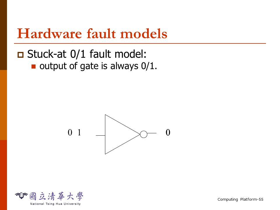
Computing Platform-55 Hardware fault models Stuck-at 0/1 fault model: output of gate is always 0/1. 0010
57
Computing Platform-56 Combinational testing Every gate can be stuck-at-0, stuck-at-1. Usually test for single stuck-at-faults. One fault at a time. Multiple faults can mask each other. We can generate a test for a gate by: controlling the gate’s input; observing the gate’s output through other gates.

58
Computing Platform-57 Sequential testing A state machine is combinational logic + registers. Sequential testing is considerably harder. A single stuck-at fault affects the machine on every cycle. Fault behavior on one cycle can be masked by same fault on other cycles.

59
Computing Platform-58 Scan chains A scannable register operates in two modes: normal; scan---forms an element in a shift register. Using scan chains reduces sequential testing to combinational testing. Unloading/unloading scan chain is slow. May use partial scan.

60
Computing Platform-59 Test generation Automatic test pattern generation (ATPG) programs: produce a set of tests given the logic structure. Some faults may not be testable---redundant. Timeout on a fault may mean hard-to-test or untestable.

61
Computing Platform-60 Boundary scan Simplifies testing of multiple chips on a board. Registers on pins can be configured as a scan chain.

62
Computing Platform-61 Outline CPU Bus and DMA Memory and I/O Devices Component Interfacing Designing with Microprocessors Development, Debugging, Testing Design Example: Alarm Clock

63
Computing Platform-62 Alarm clock interface Alarm on Alarm off Alarm ready set time set alarm hourminute light button PM buzzer

64
Computing Platform-63 Operations Set time: hold set time, depress hour, minute. Set alarm time: hold set alarm, depress hour, minute. Turn alarm on/off: depress alarm on/off.

65
Computing Platform-64 Alarm clock requirements

66
Computing Platform-65 Alarm clock class diagram Lights*DisplayMechanism Buttons* Speaker* 11 11 1 1 1 1

67
Computing Platform-66 Alarm clock physical classes Lights* digit-val() digit-scan() alarm-on-light() PM-light() Buttons* set-time(): boolean set-alarm(): boolean alarm-on(): boolean alarm-off(): boolean minute(): boolean hour(): boolean Speaker* buzz()
 digit-scan() alarm-on-light() PM-light() Buttons* set-time(): boolean set-alarm(): boolean alarm-on(): boolean alarm-off(): boolean minute(): boolean hour(): boolean Speaker* buzz()")
68
Computing Platform-67 Display class Display time[4]: integer alarm-indicator: boolean PM-indicator: boolean set-time() alarm-light-on() alarm-light-off() PM-light-on() PM-light-off()
![Computing Platform-67 Display class Display time[4]: integer alarm-indicator: boolean PM-indicator: boolean set-time() alarm-light-on() alarm-light-off() PM-light-on() PM-light-off()](http://images.slideplayer.com/13/3944764/slides/slide_68.jpg "Computing Platform-67 Display class Display time[4]: integer alarm-indicator: boolean PM-indicator: boolean set-time() alarm-light-on() alarm-light-off() PM-light-on() PM-light-off()")
69
Computing Platform-68 Mechanism class Mechanism Seconds: integer PM: boolean tens-hours, ones-hours: boolean tens-minutes, ones-minutes: boolean alarm-ready: boolean alarm-tens-hours, alarm-ones-hours: boolean alarm-tens-minutes, alarm-ones-minutes: boolean scan-keyboard() update-time()
 update-time()")
70
Computing Platform-69 Update-time behavior update seconds with rollover update hh:mm with rollover Rollover? T F PM=truePM=false AM->PM PM->AM display.set-time(current time) Time >= alarm and alarm-on? alarm.buzzer(true) T F
 Time >= alarm and alarm-on. alarm.buzzer(true) T F.")
71
Computing Platform-70 Scan-keyboard behavior compute button activations alarm-ready= true alarm-ready= false alarm.buzzer(false) Increment time tens w. rollover and AM/PM Increment time ones w. rollover and AM/PM save button states Alarm-on Alarm-off Set-time and not set-alarm and hours Set-time and not set-alarm and minutes

72
Computing Platform-71 System architecture Includes: periodic behavior (clock); aperiodic behavior (buttons, buzzer activation). Two major software components: interrupt-driven routine updates time; foreground program deals with buttons, commands.

73
Computing Platform-72 Interrupt-driven routine Timer probably can’t handle one-minute interrupt interval. Use software variable to convert interrupt frequency to seconds.

74
Computing Platform-73 Foreground program Operates as while loop: while (TRUE) { read_buttons(button_values); process_command(button_values); check_alarm(); }
 { read_buttons(button_values); process_command(button_values); check_alarm(); }")
75
Computing Platform-74 Testing Component testing: test interrupt code on the platform; can test foreground program using a mock-up. System testing: relatively few components to integrate; check clock accuracy; check recognition of buttons, buzzer, etc.

Similar presentations


 Interfacing concepts. Introduction Overview of I/O operations Programmed I/O – Standard I/O – Memory Mapped I/O Device synchronization Readings:>")

