Download presentation
Presentation is loading. Please wait.

1
Universal Serial Bus System Architecture (2)
")
2
Physical layer Data Encoding/Decoding The USB employs NRZI data encoding when transmitting packets. In NRZI encoding, a “1” is represented by no change in level and a “0” is represented by a change in level. Bit Stuffing In order to ensure adequate signal transitions, bit stuffing is employed by the transmitting device when sending a packet on USB A zero is inserted after every six consecutiveones in the data stream before the data is NRZI encoded, to force a transition in the NRZI data stream. gives the receiver logic a data transition at least once every seven bit times to guarantee the data and clock lock.

3
The Example of NRZI and Bit Stuffing

5
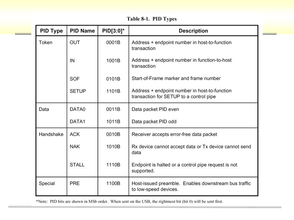
Protocol Layer- Token Packet format SYNCPIDAddressEndpointCRC Bit Ordering Bits are sent out onto the bus least-significant bit (LSB) first SYNC Field All packets begin with a synchronization (SYNC) field, which is a coded sequence that generates a maximum edge transition density. The SYNC field pattern is 00000001 Packet Identifier Field (PID) identify the packet is the token, data, and handshake packets PID[7:4]=PID[3:0]# 8-bit 7-bit4-bit5-bit
 identify the packet is the token, data, and handshake packets PID[7:4]=PID[3:0]# 8-bit 7-bit4-bit5-bit.")
7
Address(7-bit) 用來定址最多 127 個週邊裝置, 但位址 0 為 default address. endpoint(4-bit) 可看成微管線, 為每個 device 內的 register ( 或窗口 ), 最多一個 device 有 32 個 endpoint (16* (IN/OUT)), endpoint 00 為 default communication point. crc (cycle redundancy checks, 5-bit) covers the ADDR and ENDP fields of IN, SETUP, and OUT tokens or the time stamp field of an SOF token. The generator polynomial is: G(X) = X 5 + X 2 + 1
 可看成微管線, 為每個 device 內的 register ( 或窗口 ), 最多一個 device 有 32 個 endpoint (16* (IN/OUT)), endpoint 00 為 default communication point. crc (cycle redundancy checks, 5-bit) covers the ADDR and ENDP fields of IN, SETUP, and OUT tokens or the time stamp field of an SOF token. The generator polynomial is: G(X) = X 5 + X")
8
Data Packet format PID 為 data0 或 data1 最初的資料封包都以 DATA0 為開始, 其後才是 DATA1, 然後依此方式 交替切換, 此動作稱為 DATA TOGGLE 可確保整個傳輸過程中, 主機能與 DEVICE 維持同步 根據不同的傳輸型態, 其 data field 的長度限制將不同 控制型傳輸的 DATA FIELD 固定為 8-BYTE 中斷型傳輸在全速度傳輸時 data 為 64 bytes ,慢速傳輸僅為 8 bytes ,當資料小於設定值時,就表示最後一次的傳輸了 巨量型傳輸之 data 最大限制為 8 、 16 、 32 or 64 bytes 即時傳輸之 data 可為 0~1023 bytes CRC is a 16-bit polynomial applied over the data field of a data packet. The generating polynomial is: G(X) = X 16 + X 15 + X 2 + 1 SYNCPIDDATACRC 8-bit 0 ~1023 bytes16-bit
 = X 16 + X 15 + X SYNCPIDDATACRC 8-bit 0 ~1023 bytes16-bit.")
9
Handshake Packet 與 SOF Packet 接收端對傳送端送過來的資料回應 Handshake packet 有下列三種 Ack packet : device 己成功接收資料 Nak packet : device 尚未就緒 Stall packet :發生接收錯誤 SOF packet 是用於即時型傳輸 讓 device 可利用 SOF packet 來辨識 frame 的起點 即在 1ms 的 frame 開始時, 即時型傳輸會利用 SOF 啟動傳輸並達到同步傳 輸的作用. SYNCPID 8-bit Handshake packet SYNCPIDFrame numberCRC 8-bit 11-bit 5-bit Start of Frame packet

11
Transaction Format Packet transaction format varies depending on the endpoint type. There are four endpoint types: bulk, control, interrupt, and isochronous. Bulk Transactions guarantee error-free delivery of data between the host and a function By means of error detection and retry. use a three-phase transaction token, data, and handshake packets token packetdata packet handshake packet

13
Bulk Transfer

14
Control Transfers have two or three transaction stages: Setup and Status. May optionally contain a Data stage between the Setup and Status stages. SETUP stage SETUP transaction is used to transmit information to the control endpoint of a function.

15
Control Transfers Data stage consists of one or more IN or OUT transactions follows the same protocol rules as bulk transfers (consisting three packet, token, data, handshake). All the transactions in the Data stage must be in the same direction all INs or all OUTs The amount of data to be sent during the data phase and its direction are specified during the Setup stage. If the amount of data exceeds the prenegotiated data packet size, the data is sent in multiple transactions (INs or OUTs) that carry the maximum packet size. Any remaining data is sent as a residual in the last transaction.
 that carry the maximum packet size. Any remaining data is sent as a residual in the last transaction..")
16
Status stage is the last operation of control transfer in the sequence. A status stage is delineated by a change in direction of data flow from the previous stage and always uses a DATA1 PID.

17
The Status stage reports to the host the outcome of the previous Setup and Data stages of the transfer. Three possible results may be returned: The command sequence completed successfully. The command sequence failed to complete. The function is still busy completing command.

18
Control Transfer – three stages

19
Example of Control Transfer (1) device 剛連上 USB 界面時, 其 default 位址為 0, 主機利 用 default 位址向其取得 device descriptor(get_descriptor), 才知此 device 是做何用途, 將以何種傳輸方式來傳送資料, 其 device driver 為何, 等等. 因此, pc 端必需先執行一 setup token packet, 做 為 get_descriptor 的 transaction 的開始. 1.hsot -> token packet SYNCSETUPADDRENDPCRC-5 000000010XB4OX000X00X08

20
在 setup token packet ( 為控制型傳輸 ) 後面所接的 data packet 為 Example of Control Transfer (2) 2. 主機 data packet SYNCDATA0DATACRC-16 000000010xc3 80 06 00 01 00 00 00 12 0XC369 控制型傳輸的 DATA FIELD 固定為 8-BYTE

21
Example of Control Transfer (3) handshake packet 3. device -> handshake packet SYNCACK 000000010X4B
 handshake packet 3. device -> handshake packet SYNCACK X4B")
22
Interrupt Transactions may consist of IN or OUT transfers. the data toggle protocol must be followed.

23
Interrupt Transfer

24
Isochronous Transactions have a token and data phase, but no handshake phase, The host issues either an IN or an OUT token followed by the data phase in which the endpoint (for INs) or the host (for OUTs) transmits data.
 or the host (for OUTs) transmits data.")
Similar presentations


 ;而另一些 事件則會受到該事件現階段的狀況影響。>")
和全或項(最大項)展開式>")


 超過 1 的陣列則均可視 為「多維陣列」 (Multidimesional Arrays , 簡稱 N-D Arrays)>")


