Download presentation
Presentation is loading. Please wait.

2
PWM What is PWM signal? A square wave form with two parameters: 1. PWM period (T PWM ) and 2. Duty cycle (d)
 and 2. Duty cycle (d).")
3
The duty cycle is defined as the percentage of digital ‘high’ to digital ‘low + high ’ signals present during a PWM period. It is shown in the figure below, (10%, 50%, 90%). The PWM resolution is defined as the maximum number of pulses that you can pack into a PWM period. The PWM period is an arbitrarily time period in which PWM takes place. It is chosen to give best results for your particular use.
. The PWM resolution is defined as the maximum number of pulses that you can pack into a PWM period. The PWM period is an arbitrarily time period in which PWM takes place. It is chosen to give best results for your particular use..")
4
Duty cycle/ Duty Time Duty time is the ‘ON’ time in one period. (t d ). t d <T PWM Duty cycle can be determined using following eq.:
. t d <T PWM Duty cycle can be determined using following eq.:.")
5
Uses of PWM 1) Create an analog output voltage level digitally. PWM can adjust the average value of the output voltage. – Thermal system – DC Motor speed controllers – Lighting control – Any application where you need a variable DC voltage 2) To digitally create analog signals for arbitrary waveforms, sounds, music and speech.
 To digitally create analog signals for arbitrary waveforms, sounds, music and speech..")
6
SMPS application System is a DC-DC converter that regulates the output power. Power-electronic switch is used as a chopper to adjust the average value of the output voltage. PWM signal is applied to the control input (for MOSFET: gate). System has high efficiency, high performance and smaller size if it is compared to linear regulators. Duty ratio of the pwm signal is controlled by uC according to the output voltage feedback. The higher PWM frequencies produce smoother output DC voltage. However high PWM frequency increases the susceptibility to voltage noises.
. System has high efficiency, high performance and smaller size if it is compared to linear regulators. Duty ratio of the pwm signal is controlled by uC according to the output voltage feedback. The higher PWM frequencies produce smoother output DC voltage. However high PWM frequency increases the susceptibility to voltage noises..")
7
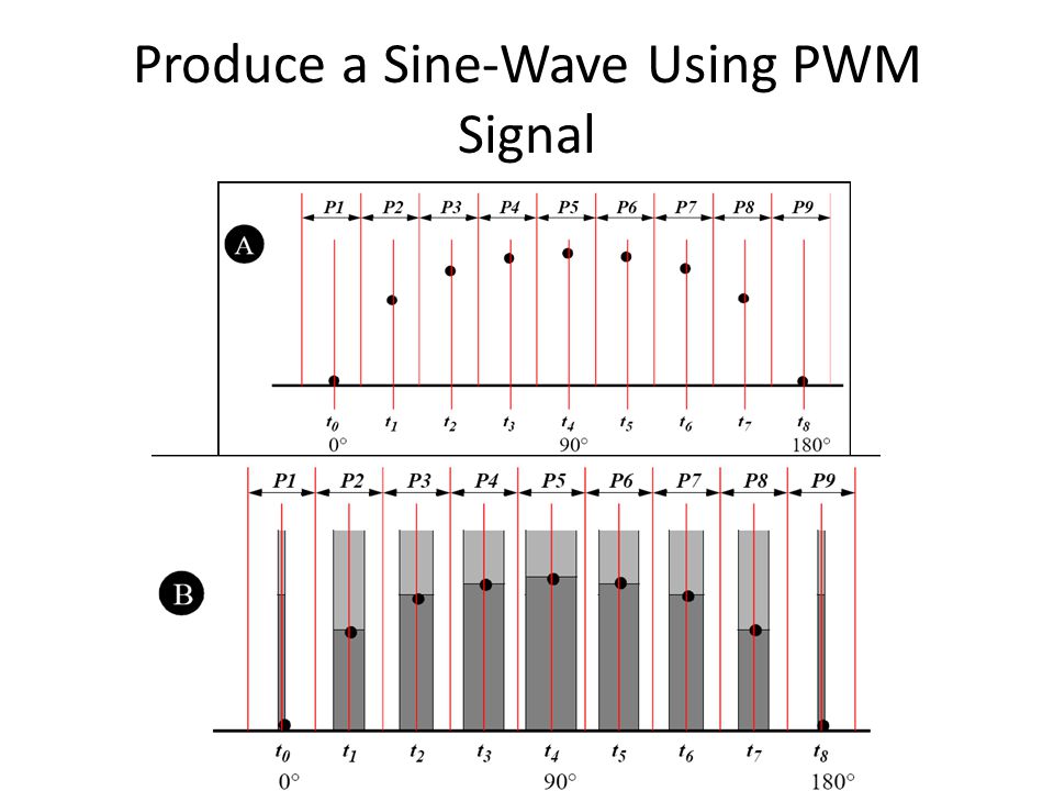
Produce a Sine-Wave Using PWM Signal

9
PWM Signal Generation

10
Before&After Filtering The filter output for higher frequency PWM input.

11
STM32F4x PWM operation The timer modules are used to generate PWM signals Most of timer modules has output channels that are assigned to I/O pins. Most of them are defined as Auxiliary Function pins.

12
Output Pins of Timer Module Channels The channel list fot TMR1 and TMR2 can be seen below. The complete channel list can be seen on table.9 in the STM32f4x datasheet (Doc#: DocID022152 Rev 4 ).
..")
14
Adjusting the PWM Signal 1.A PWM output channel should be selected 2.Proper clock signals are applied – RCC_APB1PeriphClockCmd(RCC_APB1Periph_TIM4, ENABLE);// IO PD15 is selected and it is PD15 is connected to TMR4 channel4.=> corresponding timer should be clocked – /* LED is on GPIOD, We want the LED connected to PD15 should blink*/ – RCC_AHB1PeriphClockCmd(RCC_AHB1Periph_GPIOD, ENABLE); – GPIO_InitStructure.GPIO_Pin = GPIO_Pin_15; //PD15 is selected – GPIO_InitStructure.GPIO_Mode = GPIO_Mode_AF; //Auxiliary mode is seleceted. // (Not input or not output or not Analog) – GPIO_InitStructure.GPIO_Speed = GPIO_Speed_100MHz; – GPIO_InitStructure.GPIO_OType = GPIO_OType_PP; // push pull output (not open //drain). – GPIO_InitStructure.GPIO_PuPd = GPIO_PuPd_UP ; // Pull up enable – GPIO_Init(GPIOD, &GPIO_InitStructure); – GPIO_PinAFConfig(GPIOD, GPIO_PinSource15, GPIO_AF_TIM4);// PD15 is connected to TMR4 channel4. => Configure PD15 auxiliary mode for TIM4. (GPIO_AF_TIM4)
 – GPIO_InitStructure.GPIO_Speed = GPIO_Speed_100MHz; – GPIO_InitStructure.GPIO_OType = GPIO_OType_PP; // push pull output (not open //drain). – GPIO_InitStructure.GPIO_PuPd = GPIO_PuPd_UP ; // Pull up enable – GPIO_Init(GPIOD, &GPIO_InitStructure); – GPIO_PinAFConfig(GPIOD, GPIO_PinSource15, GPIO_AF_TIM4);// PD15 is connected to TMR4 channel4. => Configure PD15 auxiliary mode for TIM4. (GPIO_AF_TIM4).")
15
2. The corresponding timer is adjusted according to the required PWM period: – /* Time base configuration */ – TIM_TimeBaseStructure.TIM_Period = 1000;// a timer period is divided into 1000 pieces. – TIM_TimeBaseStructure.TIM_Prescaler = (int) ((SystemCoreClock /2) / 50000) - 1; – TIM_TimeBaseStructure.TIM_ClockDivision = 0; – TIM_TimeBaseStructure.TIM_CounterMode = TIM_CounterMode_Up; – TIM_TimeBaseInit(TIM4, &TIM_TimeBaseStructure); Here timer4 is adjusted to 1/50msec x1000=1/50 sec. Therefore PWM period is adjusted as 20 msec. and 20 msec is divided into 1000 A PWM period has 1000x0.02 msec. time slots.
 ((SystemCoreClock /2) / 50000) - 1; – TIM_TimeBaseStructure.TIM_ClockDivision = 0; – TIM_TimeBaseStructure.TIM_CounterMode = TIM_CounterMode_Up; – TIM_TimeBaseInit(TIM4, &TIM_TimeBaseStructure); Here timer4 is adjusted to 1/50msec x1000=1/50 sec. Therefore PWM period is adjusted as 20 msec. and 20 msec is divided into 1000 A PWM period has 1000x0.02 msec. time slots..")
16
3. Set the output channel of the timer: Use TIM_OCInitStructure, TIM_OCXInit function and TIM_OCXPreloadConfig function. Here X is channel number. – /* PWM1 Mode configuration: Channel4 */ – TIM_OCInitStructure.TIM_OCMode = TIM_OCMode_PWM1; – TIM_OCInitStructure.TIM_OutputState = TIM_OutputState_Enable; – TIM_OCInitStructure.TIM_Pulse = 0; – TIM_OCInitStructure.TIM_OCPolarity = TIM_OCPolarity_High; – TIM_OC4Init(TIM4, &TIM_OCInitStructure); // The settings are loaded to output channel4 (OC4) of TIMER4. (Remember PD15 is connected to TMR4-OC4) – TIM_OC4PreloadConfig(TIM4, TIM_OCPreload_Enable); 4. Adjust the Duty cycle: Use TIM_SetCompareX function. Here X is channel number. Remember a timer period is divided into 1000, if 25% duty is required 250 of them should be ‘1’ and the rest should be ‘0’ – TIM_SetCompare4(TIM4, 250); // 25% duty cycle Examine the test_PWM.c file in detail…
; // The settings are loaded to output channel4 (OC4) of TIMER4. (Remember PD15 is connected to TMR4-OC4) – TIM_OC4PreloadConfig(TIM4, TIM_OCPreload_Enable); 4. Adjust the Duty cycle: Use TIM_SetCompareX function. Here X is channel number. Remember a timer period is divided into 1000, if 25% duty is required 250 of them should be ‘1’ and the rest should be ‘0’ – TIM_SetCompare4(TIM4, 250); // 25% duty cycle Examine the test_PWM.c file in detail….")
Similar presentations


>")


>")

>")


 LED Dimmer Circuit>")
 Dr. Zainal Salam, UTM-JB 1 Chapter 3 DC to DC CONVERTER (CHOPPER) General Buck converter Boost converter.>")