Download presentation
Presentation is loading. Please wait.

1
Group 3- Zach Hallowell (leader) Greg Rolph Mitch Miller Rob Sutton Mark Adrean
 Greg Rolph Mitch Miller Rob Sutton Mark Adrean")
2
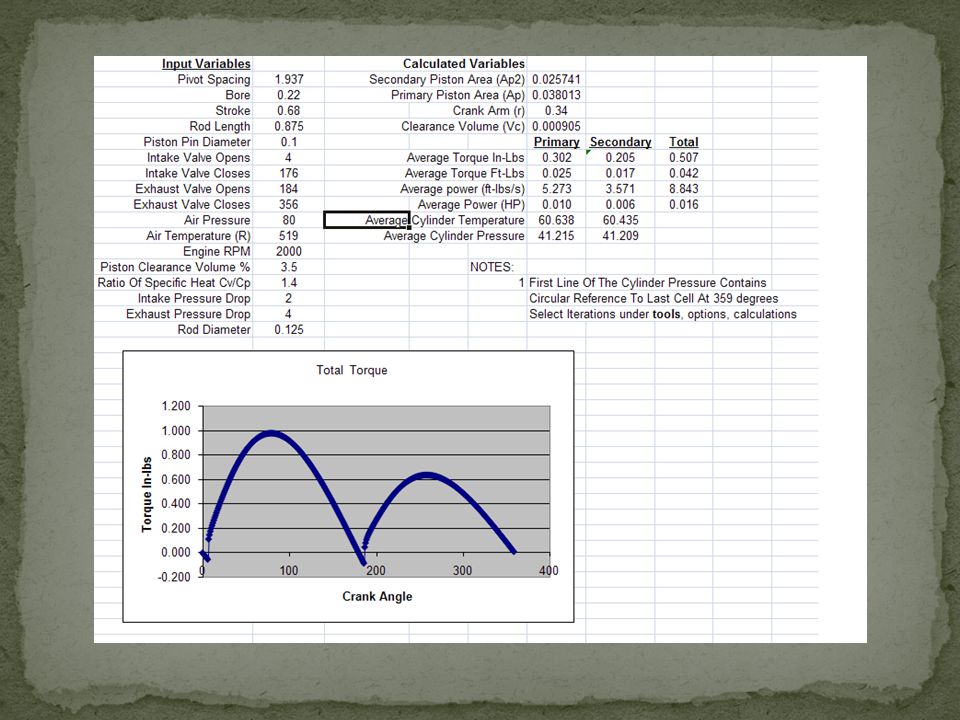
Marketing has determined that we need to double the power output of the prototype motor with the same inlet pressure. The new pressure for this application will be 80 PSI. The new motor had to power a conveyor belt.

3
Our Air Motor doesn’t have enough power to drive a conveyor system, at 80 PSI inlet pressure.

4
Increase the net power output of the Air Engine to drive a particular conveyer system, as determined by marketing. Engineering Will Rise To the Challenge Of Making Us Number 1 In The Conveyor Drive Motor Industry

5
Create More Power Prevent Power Loss Abstraction Synthesis O-rings Cylinder End Cap Dual Action Piston Bearings Adjustable Piston Rod

6
In using the first simulator we found our net output for the original air engine. With this information, we now have a goal to reach with the second simulator, producing more power at a higher psi. Our group was only 4% off to finding an exact gain from the first simulator.

8
Single (Sim. 1)20psi80psiNetDoubled% Off 1.218 lbs-ft/s7.307 lbs-ft/s6.089 lbs-ft/s12.178 lbs-ft/s0.00% Double (Sim. 2)2.486 lbs-ft/s9.103 lbs-ft/s6.617 lbs-ft/s13.234 lbs-ft/s0.08% 2.486 lbs-ft/s8.973 lbs-ft/s6.487 lbs-ft/s12.974 lbs-ft/s0.06% 2.486 lbs-ft/s8.843 lbs-ft/s6.357 lbs-ft/s12.714 lbs-ft/s0.04%
20psi80psiNetDoubled% Off lbs-ft/s7.307 lbs-ft/s6.089 lbs-ft/s lbs-ft/s0.00% Double (Sim. 2)2.486 lbs-ft/s9.103 lbs-ft/s6.617 lbs-ft/s lbs-ft/s0.08% lbs-ft/s8.973 lbs-ft/s6.487 lbs-ft/s lbs-ft/s0.06% lbs-ft/s8.843 lbs-ft/s6.357 lbs-ft/s lbs-ft/s0.04%.")
9
One of the greatest improvements that we made was to create a dual acting piston design. In the simulator we found that there was more power than needed. Changes were made for correct net output.

10
Bolt the Cylinder Plate to the wobbler Base. Press the crank bearing into the cylinder plate Press the Pivot bearing into the Cylinder plate Assemble the crank assembly. The crank pin is pressed into the crank disk The crank rotator shaft now gets pressed into the crank disk Insert the crank assembly through the crank bearing in the cylinder plate and secure it to the flywheel with the flywheel set screw. Press the pivot shaft into the cylinder Insert the cylinder/ pivot shaft assembly through pivot bearing in the cylinder plate Fasten the cylinder / pivot shaft assembly to the cylinder plate with the spring and the pivot shaft nut. Insert the piston into the cylinder Place the cylinder cap on the end of the cylinder, and fasten it with the Cylinder end cap and four screws. Join the piston rod to the crank disk pin.

11
Dual Action Piston -The previous design was with only one set of intake and exhaust ports. In the new design we have 2 sets of intake and exhaust ports. The piston now has help from both sides during one complete rotation giving us more power per stroke. O-rings - Used for sealing multiple sections of the cylinder to prevent any air from leaking out. Also used on the piston to ensure no loss with the use of a dual acting piston.

12
Bearings - Bearings were added where the was the most friction and that is on the crank shaft and pivot shaft. Bearings will help the engine run more efficient than the previous design.

13
Zach Hallowell – myweb.wit.edu/hallowellz Mark Adrean – myweb.wit.edu/adreanm/home/home.htm Mitch Miller – myweb.wit.edu/millerm4/eportfolio- 2.htm Rob Sutton - myweb.wit.edu/suttonr/classes/classes.htm Greg Rolph -

14
Rod End · Start sketch on right plane and draw.250” circle · Extrude.250” · On one end of the cylinder ends sketch an inner circle of.150” · Extrude.250” · Show top plane and draw circle of.128” · Dimension to center of top plane and.125 from back edge of cylinder · Extrude cut from mid plane through all · Last apply threads to the cylinder of.150” diameter

15
Crank bearing (sleeve) 1.) Right click on the front plane, create new sketch. 2.) Create a circle with a diameter of.250”. 3.) Extrude the circle to.250”. 4.) Create a new sketch on the front plane of the circle. 5.) Draw a circle with a diameter of.125”. 6.) Extrude cut the circle through all. 2-006 O-RING 1.) Right click on the front plane, create a new sketch. 2.) Draw a centerline with the centerline tool. 3.) Create a circle to the left of the center line with a.050” diameter. 4.) Smart dimension from the center of the circle to the center line to be.0575”. 5.) Revolve the circle around the center line.
 Create a circle with a diameter of ) Extrude the circle to ) Create a new sketch on the front plane of the circle. 5.) Draw a circle with a diameter of ) Extrude cut the circle through all O-RING 1.) Right click on the front plane, create a new sketch. 2.) Draw a centerline with the centerline tool. 3.) Create a circle to the left of the center line with a.050 diameter. 4.) Smart dimension from the center of the circle to the center line to be ) Revolve the circle around the center line..")
16
Pivot Shaft Nut 1.Import nut from design library 2.Modify interior dimension to.25 inches Cylinder Cap 1.Start by making a square with.75 inch sides 2.Make a.28 inch hole through the middle 3.Next, using the 3 point arc tool, make.38 inch diameter arcs at the four corners of the square. 4.Trim the rest of the square outside of the arcs 5.Make a.02 inch diameter hole in each of the four sections of the cap.19 inches in from the top and side.

17
Mark Adrean Cylinder Plate Flow Chart: 1. Draw base rectangle 2 inches by three inches. 2. Extrude base rectangle to five eights of an inch thick 3. Draw another rectangle on the bottom center of extrusion one. Dimension this rectangle to one quarter of an inch deep, and two inches long. 4. Now click on the front Plane, and draw two quarter inch diameter circles. The first one is going to be in the top left corner. The center of this circle should be five hundred and sixty-three thousandths in from the left and three hundred and seventy-five thousandths down from the top. The other circle will be in the top right corner. The center of this second circle will be one half inch in from the right, and three hundred and seventy-five thousandths down from the top. 5. The next step would be to extrude cut both of the circles from step four, all the way through the plate. 6. Following step five, now I drew and extruded the holes in the bottom of the plate that would align with the holes in the wobbler base. These holes in the bottom of the cylinder plate will be threaded so as to bolt the wobbler base to the cylinder plate. 7. I then drew the four circles that surround the hole in the upper right corner of cylinder plate. Once these circles were drawn, I extruded them to a depth of four tenths of an inch. These holes will form the intake and exhaust ports of the wobbler. 8. With the holes that are now extruded from step seven, I was now able to draw and extrude the hole in the left side of the plate that would act as the intake plenum for the intake ports. 9. Now the last step was to draw and extrude the two holes on the top of the cylinder plate. These holes would form the exhaust ports. These holes measure one quarter of an inch in diameter and are three tenths of an inch deep.

18
Flow Chart: 1. Create a circle using the circle tool. 2. Dimension the circle to 0.050” 3. Draw a centerline to the right of the circle. 4. Make the distance from the center of the created circle to the centerline 0.146”. 5. Click the Revolve tool from the Feature toolbar. 6. Use the created centerline as the axis of revolution. 7. Click the green check mark to finish the part.

Similar presentations


>")


