Download presentation
Presentation is loading. Please wait.

1
Mechanisms of Terahertz Radiation Generation in Graphene Structures Institute for Nuclear Problems, Belarus State University, Belarus The XII-th International School-Seminar The Actual Problems of Microworld Physics Gomel, Belarus, July 22 - August 2, 2013

2
1.Motivation; 2.Some facts about some graphene structures; 3.Demand for new Terahertz sources; 4.Brief review of ideas and achievements in the field of graphene based terahertz sources; 5.Our ideas and proposals; 6.Conclusion

3
Graphene Graphene, a 2-dimensional flat monolayer of carbon atoms arranged in a honeycomb lattice, is a promising candidate to be the basic building material for nanoscale electronic applications. Due to the hexagonal lattice structure of graphene, an interesting and elegant electronic structure arises, namely that of a gapless semi-metal with a linear dispersion relation in the vicinity of the Fermi level at the K-points in the Brillouin zone. Graphene was discovered experimentally in 2004 [K.S. Novoselov et al., Science 306, 666 (2004)].
]..")
4
Some interesting facts about graphene CERN on one’s desk: Dirac electrons Klein tunnelling: Experimental confirmation of the Klein tunnelling: Stander, Huard &Goldhaber-Gordon, 2009; Young & Kim, 2009 Quantum Hall and other quantum effects Novoselov et. al. Nature, 2005

5
Very high room-temperature electron mobility 2.5 x 10 5 cm 2 V -1 s -1 and possibility to increase mobility to the value 2·10 6 cm²·V −1 ·s −1 Ability to sustain extremely high densities of electric current (a million times higher than copper) Moser, J., Barreiro, A. & Bachtold, A. Appl. Phys. Lett. 91, 163513 (2007). Optical absorption of exactly πα≈ 2.3 % Nair, R. R. et al. Fine structure constant defines visual transparency of graphene. Science 320, 1308 (2008).
. Optical absorption of exactly πα≈ 2.3 % Nair, R. R. et al. Fine structure constant defines visual transparency of graphene. Science 320, 1308 (2008)..")
6
Graphene bilayer

7
Unrolled circumferential vectors c for a (4,4) armchair nanotube (black arrow), a (4,0) zigzag nanotube (blue arrow) and a chiral (4,2) nanotube (red arrow) are shown on a graphene plane. a1 and a2 are the unit cell vectors of graphene. The chiral angle and the translational periodicity vector ` of the (4,2) nanotube (green arrow) are also shown. Dashed lines indicate the area spanned by c and l which corresponds to the unrolled unit cell of the (4,2) nanotube.
 nanotube (green arrow) are also shown. Dashed lines indicate the area spanned by c and l which corresponds to the unrolled unit cell of the (4,2) nanotube..")
8
CARBON NANOTUBE – quasi-one-dimensional carbon macromolecula Graphene crystalline lattice SWCNT (m,n) R c =ma 1 +na 2 (m,0) for zigzag CNT (m,m) for armchair CNT The typical CNT radius ~ 1-20 nm, CNT length ~ 10 nm- few cm
 R c =ma 1 +na 2 (m,0) for zigzag CNT (m,m) for armchair CNT The typical CNT radius ~ 1-20 nm, CNT length ~ 10 nm- few cm")
9
FIG. a) A typical structure of nanoribbons. A solid circle stands for a carbon atom with one electron, while an open circle for a different atom such as a hydrogen. A closed area represents a unit cell. It is possible to regard the lattice made of solid circles as a part of a honeycomb lattice. b) A nanoribbon is constructed from a chain of m connected carbon hexagons, as depicted in dark gray, and by translating this chain by the translational vector T=qa+b, q<m. A nanoribbon is indexed by a set of two integers (p,q) with p=m−q. Motohiko Ezawa PHYSICAL REVIEW B 73, 045432 2006. (p,0) zigzag nanoribbons; ( p,1) armchair nanoribbons.
 A nanoribbon is constructed from a chain of m connected carbon hexagons, as depicted in dark gray, and by translating this chain by the translational vector T=qa+b, q<m. A nanoribbon is indexed by a set of two integers (p,q) with p=m−q. Motohiko Ezawa PHYSICAL REVIEW B 73, (p,0) zigzag nanoribbons; ( p,1) armchair nanoribbons..")
10
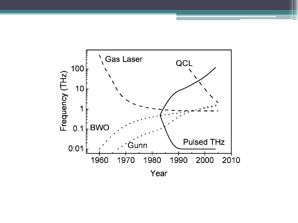
THz: Unexplored Territory

11
Applications? THz spectroscopy/imaging Radar Biology, medicine Communications Signal processing High speed computers …?

13
Plasmon amplification A.Bostwick, T. Ohta, T. Seyller, Karsten Horn, E. Rotenberg, Nature, 3, 36, (2007); Rana F. Graphene terahertz plasmon oscillators. IEEE Trans. NanoTechnol. 7, 91–99 (2008) Cherenkov-type emissions in nanotubes and graphene Harmonic generation, Rabi oscillations and Rabi-waves.
; Rana F. Graphene terahertz plasmon oscillators. IEEE Trans. NanoTechnol. 7, 91–99 (2008) Cherenkov-type emissions in nanotubes and graphene Harmonic generation, Rabi oscillations and Rabi-waves..")
14
Rana F. Graphene terahertz plasmon oscillators. IEEE Trans. NanoTechnol. 7, 91–99 (2008) Experimental observation Taiichi Otsuji1, Hiromi Karasawa1, Tsuneyoshi Komori1, Takayuki Watanabe and Victor Ryzhii 2010. Electron-hole injection O. V. Kibis, M. Rosenau da Costa, M. E. Portnoi, Generation of Terahertz Radiation by Hot Electrons in Carbon Nanotubes NanoLetters, 7 (11), 3414, (2006).
 Experimental observation Taiichi Otsuji1, Hiromi Karasawa1, Tsuneyoshi Komori1, Takayuki Watanabe and Victor Ryzhii Electron-hole injection O. V. Kibis, M. Rosenau da Costa, M. E. Portnoi, Generation of Terahertz Radiation by Hot Electrons in Carbon Nanotubes NanoLetters, 7 (11), 3414, (2006)..")
15
If a fast electron moves in a periodic potential, its momentum and velocity oscillates in time with the frequency The frequency of radiation can be tuned in these devices by varying the accelerating voltage which determines the electron. S. A. Mikhailov, Graphene-based voltage-tunable coherent terahertz emitter. Phys. Rev. B 87, 115405 (2013). Dispersion law in graphene Graphene stripes Ubitron-type generator
. Dispersion law in graphene Graphene stripes Ubitron-type generator.")
16
CHERENKOV LASING IN CNT K. G. Batrakov, P. P. Kuzhir, S. A. Maksimenko, Proc.SPIE 6328, 63280Z (2006). K.G. Batrakov, O.V. Kibis, Polina P. Kuzhir, M. R. Costa, and M. E. Portnoi, Terahertz processes in carbon nanotubes. Journal of Nanophotonics, Vol. 4, 041665 (2010). K.G. Batrakov, P. P. Kuzhir, S. A. Maksimenko, Physica B: Condensed Matter, 405 3050 (2010). K. G. Batrakov, P. P. Kuzhir, S. A. Maksimenko and C. Tomsen, Phys. Rev. B 79, 125408 (2009). K. G. Batrakov, P. P. Kuzhir, and S. A. Maksimenko, Physica E 40, 1065 2008). K. G. Batrakov, P. P. Kuzhir, and S. A. Maksimenko, Physica E 40, 2370 (2008).
. K.G. Batrakov, O.V. Kibis, Polina P. Kuzhir, M. R. Costa, and M. E. Portnoi, Terahertz processes in carbon nanotubes. Journal of Nanophotonics, Vol. 4, (2010). K.G. Batrakov, P. P. Kuzhir, S. A. Maksimenko, Physica B: Condensed Matter, (2010). K. G. Batrakov, P. P. Kuzhir, S. A. Maksimenko and C. Tomsen, Phys. Rev. B 79, (2009). K. G. Batrakov, P. P. Kuzhir, and S. A. Maksimenko, Physica E 40, ). K. G. Batrakov, P. P. Kuzhir, and S. A. Maksimenko, Physica E 40, 2370 (2008)..")
17
The basis of generation in nanotubes and graphene 1) Very large current density (up to A/cm 2 ) [M. Radosavljevi´c, J. Lefebvre, and A. T. Johnson, “High-field electrical transport and breakdown in bundles of single-wall carbon nanotubes”, Phys. Rev. B 64, 241 307® (2001); S.-B. Lee, K. B. K. Teo, L. A. W. Robinson, A. S. Teh, M. Chhowalla, et al., J. Vac. Sci. Technol. B 20, 2773 (2002)]; 2) Ballistic electron transport (up to 10 μm ) [C. Berger, P. Poncharal, Y. Yi, W. A. de Heer,Ballistic Conduction in Multiwalled Carbon Nanotubes, J. Nanosci. Nanotechn., 3, 171 (2003)]; 3) The possibility of strong electromagnetic wave slowing down [G. Ya. Slepyan, S. A. Maksimenko, A. Lakhtakia, O. Yevtushenko, A. V. Gusakov, Phys. Rev. B 60, 17136 (1999)].
; S.-B. Lee, K. B. K. Teo, L. A. W. Robinson, A. S. Teh, M. Chhowalla, et al., J. Vac. Sci. Technol. B 20, 2773 (2002)]; 2) Ballistic electron transport (up to 10 μm ) [C. Berger, P. Poncharal, Y. Yi, W. A. de Heer,Ballistic Conduction in Multiwalled Carbon Nanotubes, J. Nanosci. Nanotechn., 3, 171 (2003)]; 3) The possibility of strong electromagnetic wave slowing down [G. Ya. Slepyan, S. A. Maksimenko, A. Lakhtakia, O. Yevtushenko, A. V. Gusakov, Phys. Rev. B 60, (1999)]..")
18
Interaction between electron beam and produced electromagnetic wave leads to electron beam modulation. This process can be described by self-consistent system: and for electrons : Self-consistent equations for electromagnetic field:

19
Dispersion equation Emission term Absorption term electron group velocity in nanotube

20
If width of emission line exceeds the magnitude of quantum recoil. then traditional form of second-order Cherenkov resonance is realized : Otherwise, quantum recoil contributes to resonance condition and dispersion equation has the form

21
Gain is extremely large as compared with the gain per unit length for macro- devices Boundary conditions on nanotube tips and dispersion equations give threshold condition and instability increment Threshold current and instability increment of generation

22
Generation is already possible at the current stage of nanotechnologies development. K. G. Batrakov, P. P. Kuzhir, S. A. Maksimenko, Proc.SPIE 6328, 63280Z (2006). K. G. Batrakov, P. P. Kuzhir, S. A. Maksimenko and C. Tomsen, Phys. Rev. B 79, 125408 (2009). K.G. Batrakov, O.V. Kibis, Polina P. Kuzhir, M. R. Costa, and M. E. Portnoi, Terahertz processes in carbon nanotubes. Journal of Nanophotonics, Vol. 4, 041665 (2010). K.G. Batrakov, P. P. Kuzhir, S. A. Maksimenko, Physica B: Condensed Matter, 405 3050 (2010).
. K. G. Batrakov, P. P. Kuzhir, S. A. Maksimenko and C. Tomsen, Phys. Rev. B 79, (2009). K.G. Batrakov, O.V. Kibis, Polina P. Kuzhir, M. R. Costa, and M. E. Portnoi, Terahertz processes in carbon nanotubes. Journal of Nanophotonics, Vol. 4, (2010). K.G. Batrakov, P. P. Kuzhir, S. A. Maksimenko, Physica B: Condensed Matter, (2010)..")
23
Method for the instability control The points of maximum group velocity and respectively low excitation energy can be advantageous for lasing. In the point of group velocity extremum the negative influence of the beam energy spread is smaller, and therefore more electrons interact with the wave: the radiation effectiveness can be increased. It is also possible to intensify the effect of radiation instability in nanotube due to the generation in the region of small effective mass of quasiparticle.

24
Compensation of electron beam spread Extremum of group velocity Dispersion equation Then, expansion near this point gives So, negative influence of beam spread can be reduced.

25
For long wavelength ( is the distance between nanotube layers), frequencies may be approximately presented as: Phase velocity corresponding to frequency, can be significantly less, than phase velocities corresponding to single walled nanotubes with radii !!! Estimated wave retardation in two-wall carbon nanotube reach ~ 150 times. K. G. Batrakov, P. P. Kuzhir, and S. A. Maksimenko, Electrical and Computer Engineering Series archive,Proceedings of the 1st WSEAS international conference on Nanotechnology table of contents,Cambridge, UK,2009, pp. 96–100. However, therefore decreasing of phase velocity in two-wall nanotube is limited. Bilayer graphene has no such drawback. Advantage of using two-layer or multilayer nanotube or graphene for emission Estimated wave retardation in single walled nanotube reach 50 times (G. Slepyan, A.Lakhtakia, S. Maksimenko…)
.")
26
Graphene bilayer

27
The basic equations Resulting self-consistent equation for potential has the form: are the wave functions of graphene bilayer

28
B. Partoens and F. M. Peeters, PHYSICAL REVIEW B 74, 075404 2006

30
irreducible polarizability

31
The root with minus “-” corresponds to antiphase (acoustic) oscillation. If kd<<1, then the phase velocity of antiphase oscillation is more less of usual one!!!

32
spatially separated double-layer graphene It can be can be fabricated by folding an single layer graphene over substrate. H. Schmidt, T. Ludtke, P. Barthold, E. McCann, V. I. Fal’ko, and R. J. Haug, Appl. Phys. Lett. 93, 172108 (2008). In spatially separated double-layer graphene electron tunneling between graphene planes can be eliminated. However, the plasmon modification still exists if kd<<1. Konstantin G. Batrakov ; Vasily A. Saroka ; Sergey A. Maksimenko ; Christian Thomsen, J. Plasmon polariton deceleration in graphene structures. Nanophoton. 6(1), 061719 (Dec 05, 2012). doi:10.1117/1.JNP.6.061719
. In spatially separated double-layer graphene electron tunneling between graphene planes can be eliminated. However, the plasmon modification still exists if kd<<1. Konstantin G. Batrakov ; Vasily A. Saroka ; Sergey A. Maksimenko ; Christian Thomsen, J. Plasmon polariton deceleration in graphene structures. Nanophoton. 6(1), (Dec 05, 2012). doi: /1.JNP")
33
The electromagnetic wave frequency (1/s) versus wave vector k (1/cm).
 versus wave vector k (1/cm).")
34
Harmonic generation in terahertz range Odd harmonics generation

35
One-photon and multi-photon Rabi oscillation

36
Rabi oscillation and harmonic generation in AB-stacked bilayer graphene

37
The effect of trigonal warping on the electronic structure of bilayer graphene McCann & Falko (2006) and McCann, Abergel & Falko (2007) Cross-section of the dispersion surface General view of the dispersion surface
 and McCann, Abergel & Falko (2007) Cross-section of the dispersion surface General view of the dispersion surface")
38
In the presence of electric field the Hamiltonian has the form: After second quantization : In the Heisenberg representation dynamics is described by equation: H.K.Avettissian, G.F.Mkrtchian, K.G.Batrakov, S.A.Maksimenko, Nonlinear Interactions of Coherent Radiation with Bilayer Graphene and High Harmonic Generation, Physics, Chemistry and application of Nanostructures, p.195-198, 2013.

39
Dynamics of density matrix: The method of characteristic is used for transition from partial to ordinary differential equations. The characteristic coincides to the classical electron dynamics in the electron field:

40
Parameter which characterizes electromagnetic field-graphene electron interaction Condition of n-photon process, where 1) -one photon excitation, the multiphoton effects are suppressed; 2) - multiphoton excitation.
 -one photon excitation, the multiphoton effects are suppressed; 2) - multiphoton excitation.")
41
Particle distribution function after the interaction during the 32 wave oscillation periods,χ=0.1,( a) and (b) present Dirac sea excitation of two different graphene valleys, ω=0.9 meV, (c) and (d) is for the wave frequency ω=5 meV.
 and (b) present Dirac sea excitation of two different graphene valleys, ω=0.9 meV, (c) and (d) is for the wave frequency ω=5 meV.")
42
Particle distribution function after 32 wave periods for different parameters χ: (a) χ=0.2, (b) χ=0.3,(c) χ=0.4,(d) χ=0.5, ω=10 meV, T/ω=0.01.
 χ=0.2, (b) χ=0.3,(c) χ=0.4,(d) χ=0.5, ω=10 meV, T/ω=0.01.")
43
Temperature dependence: ω=8 meV, χ=0.5, (a) T/ω=3, (b) T/ω=1, (c) T/ω=0.1, (d) T/ω=0.01
 T/ω=3, (b) T/ω=1, (c) T/ω=0.1, (d) T/ω=0.01")
44
Harmonics generation The emission rate of the n-th harmonic is proportional to the n-th Fourier components of the field-induced current:

45
Harmonic emission rate at the multiphoton excitation in bilayer graphene for different parameters χ:(a) χ=0.2, (b) χ=0.3,(c) χ=0.4,(d) χ=0.5, ω=1 meV.
 χ=0.2, (b) χ=0.3,(c) χ=0.4,(d) χ=0.5, ω=1 meV.")
46
Required Intensities The wave intensity can be expressed through the χ parameter as: Therefore for THz photons (wavelengths from 30 μm to 3 mm), multiphoton interaction regime can be achieved at the intensities 10 – 10 5 W cm -2. So, with radiation fields of moderate intensities ∼ 3 kW cm −2 in the THz domain one can observe multiphoton excitation of Fermi-Dirac sea and efficient generation of moderately high harmonics in the bilayer graphene.

47
Graphene structure is very perspective material for terahertz nanoelectronics. Conclusion

48
БРФФИ № Ф06Р-101, БРФФИ № Ф08Р-009, БРФФИ № Ф11АРМ-006, EU FP7 TerACan project FP7-230778, BMBF(Germany) project BLR 08/001, EU FP7 CACOMEL project FP7-247007, EU FP7 BY-NanoERA project FP7-266529, Call ID FP7-INCO-2010-6, 2010- 2013.. Acknowledgments

49
Thank you for attention

Similar presentations


>")
. - 2010 Nobel Prize in Physics Q1. How.>")

 –8 C atoms.>")


 Symmetry operations Line groups Part II (December 6) Irreducible representations.>")


 are cylindrical macromolecules formed by periodic hexagonal structures of carbon atoms. The ends of NT are closed by.>")

