Download presentation
Presentation is loading. Please wait.

1
Accubeacon Andrew Gans, Spencer Curran, Shreyank Amartya, Alex Fouss, John Bullock
![]()
2
Avalanche Hazards background
Winter backcountry recreation has become increasingly popular. Thousands of skiers and sledders put themselves in dangerous avalanche zones each year 90% are caused by a victim or someone in their party. Personal Account of Avalanche Video Spencer

3
Avalanche Hazards include data on life expectancy Spencer

4
Spencer

5
Avalanche Rescue Methods
Probe line - A technique used with an abundance of searchers K9 search team - Avalanche dogs are trained to sniff out buried victims Proper Shoveling - There are several methods for fast and swift extractions Air Bag - A backpack air bag that can be deployed when victim triggers an avalanche to prevent being buried. Spencer

6
Spence

7
Other Innovations Use of sensors
1. Knowledge about the state of the victim; survival chances, urgency, vital signs. 2. Orientation of victim in snow 3. Depth of buried victim. Multiple Buried victim markers

8
Accubeacon Avalanche Transceiver
System Overview Accubeacon Avalanche Transceiver
![]()
9
Statement of Purpose To design a set of avalanche transceivers that can communicate with each other to allow for more accurate pinpointing of buried victims and multiple burial detection Spencer

10
Requirements-Primary
Level Requirement Dependencies Primary P1 Triangulate relative location of buried S1,S2,S3 P2 Display victim location in an easy to read format S4 P3 Supply enough power for extended use in the backcountry S5 P4 Meet all standard specifications and functionality of current transceivers S7,S8 P5 Detect multiple burials S6 Spencer

11
Requirements-Secondary
Level Requirement Secondary S1 Calculate distance between user beacon and buried beacon using 457kHz wireless signal S2 Calculate distance between user beacon and other searching beacons using other wireless protocol S3 Receive distance data from other searching beacons S4 Place relative location of buried victim onto visual display S5 Provide a sufficiently sized battery pack to meet power requirements S6 Determine the event of multipal burials S7 Transmit at standard 457kHz frequency S8 Incorporate standard signal strength indicator search functionality Spencer

12
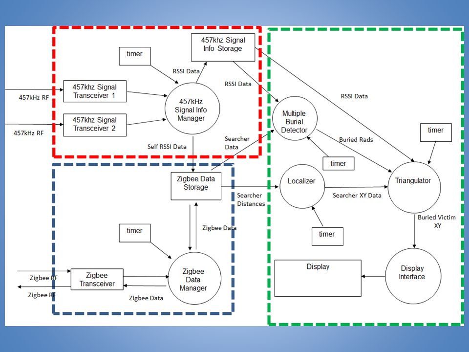
Subsystems kHz RF Transmits/receives standard 457kHz frequency signal and processes associated RSSI signal 2. ZigBee Wireless Transmits in the ISM band and uses RSSI or RTOF (round trip time of flight) to get triangulation information 4.User Interface/Data Processing Provides clear and concise information about the location of burial Alex
 to get triangulation information. 4.User Interface/Data Processing. Provides clear and concise information about the location of burial. Alex.")
14
Processing and User Interface Subsystem
Accubeacon Avalanche Transceivers

15
Processing and User Interface
Collects data from 457khz and zigbee subsystems Uses data to run required algorithms for multiple burial detection, localization and trilateration

16
Algorithms Trilateration Localization Multiple Burial Detection

17
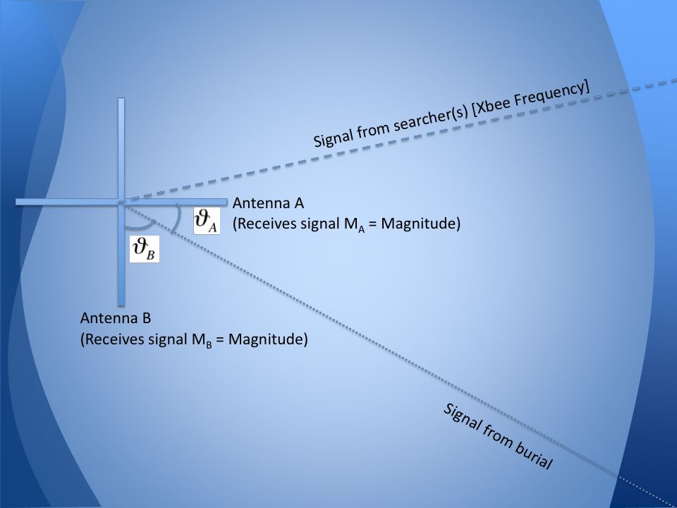
Localization Uses distances between three or more searching beacons to determine relative x,y positions of other searchers Requires accurate distance measurement between searching beacons x,y positions of other searchers allows for triangulation using 457khz signal
![]()
18
Trilateration Process
-Localization determines relative position of other searchers -Trilateration uses localized distance vectors from other searchers to compute buried location -Buried location presented to searcher via user interface Shreyank

19
Trilateration Diagram
Shreyank

20
System Setup Alex

21
Multiple Burial Detection
Use 457khz signal strength from multiple antenna and multiple beacons to determine distance from buried victim(s)
")
25
User Interface and Hardware
Requirements Processor that can run all required algorithms User interface that displays results of algorithms

26
Development Board Atmel xmega 256-A3 microcontroller Power Conversion
Serial Connectors 4.5V Battery Jack Test Pads USB connector Power and Serial LED's PDI interface for AVR ISP mkii

27
Microcontroller - ATxmega 256A3U
Past experience with Atmel microcontrollers and AVR Studio Can easily switch to a different series of Atmel microcontroller Easily accessible drivers and libraries for different peripherals and modules Can be easily programmed through PDI using Atmel mkii In System Programmer

28
User Interface Push Buttons to power on, switch between search and transmit mode LCD module to display the grid and relative positions of the searchers and victims

29
Zigbee Wireless Subsystem
Accubeacon Avalanche Transceivers

30
Tasks and Responsibilities
Sends data between searching beacons Detects RTOF/RSSI from received signal to calculate distance

31
ZigBee Display/Processing
-Received Signal Packer from Other Searchers -Distance correlation (RTOF/RSSi) Transmitted Signal Packet to Other Searchers ZigBee Modem Distance Data to Microcontroller Display/Processing Processing and Display -Triangulates burial location -Displays to screen -Distances between searchers -Distance/Angle to buried victim -Mode information Alex
 Transmitted Signal Packet to Other Searchers. ZigBee Modem. Distance Data to Microcontroller. Display/Processing. Processing and Display. -Triangulates burial location. -Displays to screen. -Distances between searchers. -Distance/Angle to buried victim. -Mode information. Alex.")
32
Module Zigbee Wireless Transceiver Level 2 Input 48 bit packets using TOA (Time of Arrival) or RTT (Round Trip Time) Output Functionality Provide adequate signal to determine distance from other searchers and transmit own 457 kHz signal to aid in trilateration. As well as receive the distance of other searchers in order to locate them compared to own reference location. Determine their 457 signal of the buried victim to aid in trilateration.

33
Wireless Distance Measurement
RSSI(Received Signal Strength Indicator) -RSSI is the measurement of power present in the received radio signal. RSSI is directly proportional the distance as follows RSSI log (P/Pref) Shreyank
 -RSSI is the measurement of power present in the received radio signal. RSSI is directly proportional the distance as follows. RSSI 10 log (P/Pref) Shreyank.")
34
Wireless Distance Measurement
Time of Arrival - Using synchronized clocks and time stamps to record signal travel time -Travel time can be correlated with distance -More accurate than RSSI but requires precise timing Shreyank

35
Wireless Packet -Currently we are using XBee libraries to transmit packet arrays amongst other searcher. -The packet contains the following data 1. Sender's XBee ID 2. 1st RF distance 3. 2nd Searchers RF distance 4. 3rd Searchers RF distance 5. Distance from 3 to 1 6. Distance from 3 to 2 7. Distance from 2 to 1 -Each individual XBee processes this data and extract all relevant data for their own array.

36
The backbone of avalanche transceivers
457 kHz RF Subsystem The backbone of avalanche transceivers

37
Other marketed beacons only have this system.
The 457 kHz subsystem is the bare minimum needed for a working avalanche beacon Other marketed beacons only have this system. Some beacons use digital signal processing and 3 axis antennas to eliminate false readings No current beacon uses communication with other searchers to correlate information and further eliminate error
![]()
38
457 kHz Transmitter 457 kHz Receiver
Transmit on (Oscillators / Filtering) USER INPUT (device power on) Ferrite Rod Antenna (2x, orthogonal) Outputs Radiation Pattern 457 kHz Receiver Ferrite Rod Antenna (2x, orthogonal) Determines Orientation Analog Front End (Filtering, Multiplexing, A/D) Directional Information to Microcontroller USER INPUT (device switched to search mode) Alex
 USER INPUT. (device power on) Ferrite Rod Antenna (2x, orthogonal) Outputs Radiation Pattern. 457 kHz Receiver. Ferrite Rod Antenna (2x, orthogonal) Determines Orientation. Analog Front End. (Filtering, Multiplexing, A/D) Directional Information to Microcontroller. USER INPUT. (device switched to search mode) Alex.")
39
457 kHz Transmitter (Level 3)
Pulsed 457 kHz 457 kHz Crystal Oscillator RF Filters MUX RF PWR AMP Demux Buffer AMP Gnd Antenna selection Frequency Divider Frequency Divider Counter pulse RF Choke Power Module 457 kHz Transmitter Level 3 Input Power Output 457 kHz pulsed RF power on either of two antennas Functionality Provide adequate radiation to allow for detection when buried ~50m away

40
Creates a DC voltage relative to received RF signal strength
457 kHz Receiver (Level 3) Antenna selection (sync with Tx) Creates a DC voltage relative to received RF signal strength 457 kHz tunning Pulsed 457 kHz Mux Band pass filter Rectifier Signal Conditioning RF AMP Out to CPU buffer 457 kHz tunning RF Choke Power Module 457 kHz Receiver Level 3 Input RF Radiation (tuned to 457 kHz), power Output Analog signal to be processed by microcontroller Functionality Provide a meaningful analog voltage that represents signal strength for each antenna orientation
 Antenna selection. (sync with Tx) Creates a DC voltage relative to received RF signal strength. 457 kHz tunning. Pulsed 457 kHz. Mux. Band pass filter. Rectifier. Signal. Conditioning. RF. AMP. Out to CPU. buffer. 457 kHz tunning. RF Choke. Power. Module. 457 kHz Receiver Level 3. Input. RF Radiation (tuned to 457 kHz), power. Output. Analog signal to be processed by microcontroller. Functionality. Provide a meaningful analog voltage that represents signal strength for each antenna orientation.")
41
Trilateration (Triangulation)
Using cross-searcher data communication reduces guesswork and ambiguity with ultimate goal of eliminating a coarse search Trilateration (Triangulation) Quick and precise pinpointing of multiple buried victims (even with unintended signal modulation - overlap)
 Quick and precise pinpointing of multiple buried victims (even with unintended signal modulation - overlap)")
42
Tasks Transmit RF signal within margin of error up to current standards (457 kHz ± 80 Hz) Differentiate signals of multiple buried victims Relay analog information to microcontroller when in search mode

43
Features Backwards Compatibility
Receive RF signals within a large margin of error (457 kHz ± 200 Hz) Covers range of frequencies for 1970's era beacons If all else fails (one searcher, no xbee communication, etc) the transceiver will function as a regular ("digital”) beacon
 Covers range of frequencies for 1970 s era beacons. If all else fails (one searcher, no xbee communication, etc) the transceiver will function as a regular ( digital ) beacon.")
44
Prototyping & Testing Multiple searcher tests done
Differences in signal waveform (BCA Tracker DTS) give signature characteristics based on buried beacon’s orientation Use the differences in signal to communicate between beacons and determine instantaneous location of buried victim This method can be extrapolated for multiple burials
 give signature characteristics based on buried beacon’s orientation. Use the differences in signal to communicate between beacons and determine instantaneous location of buried victim. This method can be extrapolated for multiple burials.")
45
Prototyping & Testing Digital signal processing
Differentiate between signal overlap and no signal overlap Smooth out signal modulation when overlapping

46
Prototyping More information is needed to reduce degrees of freedom
Searcher inputs number of burials Digital compass used to find magnetic north

48
Receiving Antennas Arrangement
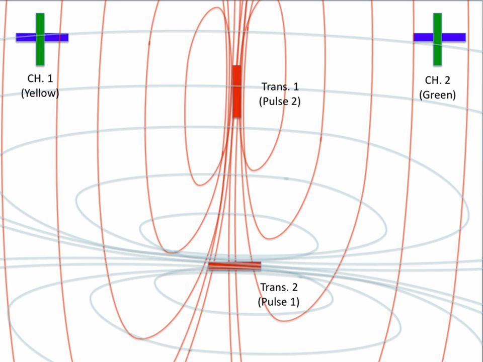
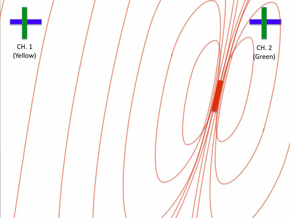
Transmitting Antenna (Buried Person) Receiving Antennas Arrangement (BCA Tracker DTS)
 Receiving Antennas Arrangement. (BCA Tracker DTS)")
50
Two Transmitters Same Relative Distances

52
1 Transmitter Closer to CH. 2

54
90 Degree Triangle

58
In H-Plane Closer to CH. 2

62
In H-Plane Tx, RxCH.1,RxCH.2 Orientation

64
Same Configuration with RxCH.2 Rotated 90 Degrees

66
Both CH. 1 and CH. 2 90 Degree Offset

67
Development Plan (Multiple Burials)
Input data into microcontroller Analog voltages converted to sampled digital signal Signal processed using differential algorithms Vectors assigned to signals and output to high-res matrix display

68
Design Approach Milestones 1. Proof of Theory
2. Rev A. - Proof Of Concept 3. Rev. B 4. Final Rev. Wheeler

69
Design So Far Completed required background research to show that the concept is feasible - Used existing beacon as test platform Incorporated Zigbee wireless: -data transmission -distance measurement Algorith Implementation on arduino Wheeler
![]()
70
Current Setup Arduino Uno Xbee BCA Tracker Beacon
Point to Point network RSSI -Distance Measurement BCA Tracker Beacon RSSI pulled from 7-Segment Display Allows for easy implementation of algorithms
![]()
72
Revision B -First PCB Revision
-Atmel Microcontroller on “development board” -Multiple Burial Algorithm Implemented -Lower Level Input from Existing Beacon -RTOF implementation Wheeler

73
Revision C - Final Rev. -Integration of our own 457kHz Transceiver
-Finalized Zigbee System -Finalized Multiple Burial Determination System -Finalized Processing/Display Wheeler

74
Team/Project Management
Wireless Communication RF Communication Multiple Burial Determination User Interface/Data Processing Spencer X Wheeler John Alex Shreyank John

75
Scheduling Tasks Along with our bi-weekly scheduled lab time, we have weekly "scrums" to discuss progress and updates on Monday nights. We do our best to set up 2 week sprints, in which we set goals and task to accomplish in order to stay on track with our milestone goals. John

76
Budget Applied for UROP and using Personal Funds. Estimated Costs
Research $102 Rev A $133 Rev B $294 Rev C Total $823 Applied for UROP and using Personal Funds. John

77
Risks and Contingencies
RSSI accuracy has not been proven, RTOF should prove to be more accurate, but we have been unsuccessful implementing 2. RF 457 kHz implementation 3. Expandability to function with N searching beacons 4. Multiple Burial Determination John

78
Conclusion -Current beacon technology is decades old
-Accuracy is going to be our biggest concern and goal -Through 2-way communication we project to minimize search time to save lives and hopefully carve out a spot in the market not yet realized John
![]()
79
Questions & Comments

Similar presentations


>")


 Group Members: Keiichi McGuireHenry Pham Marc TakamoriScott Spiro.>")


